
The Arduino Actuator Migration: Outgrowing Hobby Servos
When you first prototype an automated greenhouse vent, a robotic arm, or a motorized camera slider, standard SG90 or MG996R hobby servos are the default choice. They are cheap, widely available, and easily controlled via the Arduino Servo.h library. However, as projects transition from the workbench to real-world deployment, the mechanical and electrical limitations of these cheap components become glaringly obvious. Upgrading your Arduino actuator setup from hobby-grade PWM servos to industrial linear drives or stepper-based lead screws is a critical rite of passage for advanced makers and embedded engineers.
This migration is not merely about swapping one motor for another; it requires a fundamental overhaul of your power architecture, signal isolation, and control logic. In this 2026 migration guide, we break down exactly how to scale your actuator systems from 5V hobby toys to robust, high-force linear drives without frying your microcontroller.
Identifying the Bottleneck: When to Upgrade
Before tearing apart your existing rig, you must confirm that the actuator is the actual bottleneck. Hobby servos typically fail in field deployments due to three primary edge cases:
- Thermal Overload & Gear Stripping: Standard MG996R servos feature sintered metal gears that degrade rapidly under continuous high-torque loads, leading to positional slop.
- Current Spikes & Brownouts: A stalled 9g servo draws roughly 700mA, while a large MG996R can spike to 2.5A. This causes severe voltage sag on the 5V rail, triggering spontaneous resets on the Arduino Nano or Uno.
- Lack of Absolute Positioning Under Load: Hobby servos rely on cheap internal potentiometers that drift over time and temperature, making them unsuitable for precision automation.
Actuator Technology Comparison Matrix
Selecting the right upgrade path depends on your specific force, speed, and precision requirements. Below is a comparison of standard migration targets as of early 2026.
| Actuator Type | Example Model | Force / Torque | Control Interface | Est. Cost (2026) |
|---|---|---|---|---|
| Hobby Servo (Baseline) | TowerPro MG996R | 10 kg-cm | 5V PWM (1-2ms) | $8 |
| DC Linear Actuator | Progressive Automations PA-14 | 150 lbs (667N) | 12V DC Polarity Reversal | $115 |
| Stepper Linear Drive | NEMA 17 + T8x2 Lead Screw | ~45 Ncm (Holding) | STEP / DIR Pulses | $35 (Motor + Screw) |
| Brushless DC (BLDC) Linear | Firgelli L12-R | 25N to 100N | 0-5V Analog / 4-20mA | $140 |
Phase 1: Power Architecture Overhaul
The most common mistake during an Arduino actuator upgrade is attempting to power a 12V linear actuator using the same power supply that feeds the microcontroller's logic circuits. Industrial actuators require massive inrush currents. According to the Progressive Automations linear actuator guide, a standard 12V DC actuator can draw 10A to 15A under heavy load or stall conditions.
The Isolated Dual-Rail Approach
You must migrate to a dedicated, high-wattage switching power supply for the actuator, while keeping the Arduino on a separate, clean 5V rail. The Mean Well LRS-150-12 (12V, 12.5A) is the industry standard for this tier, costing around $28. It provides more than enough headroom for a 10A actuator while handling inductive spikes gracefully.
For the Arduino's 5V logic, do not use a cheap linear regulator (like the LM7805) stepping down from the 12V rail; the heat dissipation will be immense. Instead, use a high-efficiency synchronous buck converter like the LM2596 or MP1584EN module, dialed in to exactly 5.0V.
Phase 2: Signal Isolation and Back-EMF Protection
When migrating from a simple 5V PWM signal to high-current motor drivers, you expose your microcontroller to severe electrical noise. The Arduino motor documentation explicitly warns against driving inductive loads directly from microcontroller pins, but even using standard MOSFETs introduces risks.
Combating Inductive Kickback
Inductive kickback (back-EMF) is the silent killer of upgraded actuator projects. As detailed in Texas Instruments' application notes on motor driving, when current to an inductive load is suddenly interrupted—such as a limit switch opening or a MOSFET closing—the collapsing magnetic field generates a massive voltage spike. Without proper flyback diodes (like the 1N5819 Schottky for fast switching or 1N4007 for general rectification), this spike will travel through the shared ground plane and permanently destroy the ATmega328P or ESP32.
Implementing Optocouplers
For heavy DC linear actuators driven by a high-power motor driver like the BTS7960 (capable of 43A continuous), you should insert a PC817 optocoupler between the Arduino's digital output pins and the driver's logic inputs. The PC817 costs less than $0.50 and uses light to transmit the signal, providing 100% galvanic isolation. This ensures that if the BTS7960 fails catastrophically, the 12V/24V high-current rail cannot physically reach your $5 microcontroller.
Phase 3: Control Logic and Code Migration
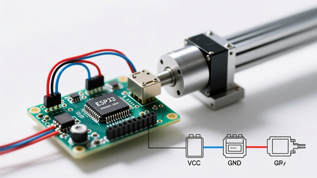
Migrating to a stepper-based linear actuator (e.g., NEMA 17 with a T8 lead screw) requires a complete paradigm shift in your firmware. You are no longer sending a 1-2ms PWM pulse to dictate an absolute angle. Instead, you are generating high-frequency STEP pulses and managing directional logic.
The Math of Stepper Linear Actuators
To write accurate positioning code using the AccelStepper library, you must calculate the exact steps per millimeter. Let us break down the exact math for a standard 2026 maker setup:
- Motor Base Steps: A standard 1.8° NEMA 17 motor yields 200 full steps per revolution.
- Microstepping: Using a TB6600 driver set to 1/16 microstepping, that becomes 3,200 steps per revolution (200 x 16).
- Lead Screw Pitch: A standard T8 lead screw has a 2mm lead (pitch). One full revolution moves the actuator nut exactly 2mm.
- Final Calculation: 3,200 steps / 2mm = 1,600 steps per millimeter.
To move the actuator exactly 50mm, your Arduino must reliably pulse the STEP pin 80,000 times. If your Arduino is handling interrupt-heavy tasks like reading encoders or managing Wi-Fi via an ESP32, you will experience missed steps and positional drift. In these edge cases, migrate your code to use hardware timer interrupts (via the TimerOne library) or upgrade to a dedicated motion controller like the TMC2209, which handles step interpolation internally.
Step-by-Step Migration Checklist
Follow this exact sequence to ensure a safe and successful upgrade from hobby servos to industrial actuators:
- Audit the Mechanical Load: Measure the exact force (in Newtons or lbs) and stroke length required. Do not overspec the actuator, as larger actuators require exponentially more power and heavier mounting hardware.
- Procure Isolated Power: Order a Mean Well LRS series PSU for the actuator and a dedicated buck converter for the 5V logic rail.
- Wire the Flyback Protection: Solder 1N5819 Schottky diodes in reverse bias across the actuator terminals before connecting them to the driver board.
- Install Optocouplers: Route your Arduino GPIO pins through PC817 optocouplers before feeding them into the BTS7960 or TB6600 driver inputs.
- Establish Common Ground: Connect the GND of the high-voltage PSU, the driver board GND, and the Arduino GND to a single, thick star-ground point.
- Implement Software Limits: Even if your physical actuator has internal limit switches, always code software limits in your firmware to prevent the actuator from ramming into the end-stops and drawing continuous stall current.
Conclusion
Upgrading your Arduino actuator from a hobby servo to a professional linear drive transforms a fragile prototype into a reliable, field-ready machine. By respecting the physics of inductive loads, isolating your power architectures, and recalculating your firmware logic for step-based precision, you eliminate the most common failure modes that plague advanced maker projects. Invest in proper drivers, use optocouplers, and let your microcontroller do what it does best: process logic, not push heavy currents.