
What is SPI? The High-Speed Serial Standard
In 2026, the Serial Peripheral Interface (SPI) remains the undisputed champion for high-speed, short-distance communication between microcontrollers and peripherals. Whether you are driving a 2.8-inch ILI9341 TFT display, reading high-frequency data from an RFM69HW radio transceiver, or interfacing with a Bosch BME280 environmental sensor, SPI delivers raw speed that I2C and UART simply cannot match.
Unlike I2C, which relies on a multi-master arbitration protocol and pull-up resistors, SPI is a strictly synchronous, master-slave (or controller-peripheral) protocol. The Arduino acts as the Controller, generating the clock signal and initiating all data transfers. This direct hardware control allows SPI to routinely achieve clock speeds of 8 MHz to 24 MHz on modern boards like the Arduino Uno R4 Minima, making it the mandatory choice for bandwidth-heavy applications like audio streaming or rapid graphical rendering.
The 4-Wire Anatomy of an SPI Bus
To successfully implement SPI for Arduino projects, you must understand the four shared logic lines. Unlike I2C's two-wire simplicity, SPI uses separate lines for sending and receiving data simultaneously (full-duplex).
| Arduino Pin (Controller) | Peripheral Pin (Sensor/Display) | Function & Direction |
|---|---|---|
| MOSI (Pin 11 on Uno) | SDI / MOSI / DIN | Master Out, Slave In: Data sent from Arduino to peripheral. |
| MISO (Pin 12 on Uno) | SDO / MISO / DOUT | Master In, Slave Out: Data sent from peripheral to Arduino. |
| SCK (Pin 13 on Uno) | SCLK / SCK / CLK | Serial Clock: Timing signal generated by the Arduino. |
| CS / SS (Any Digital Pin) | CS / SS / CE | Chip Select: Active-LOW pin to wake a specific peripheral. |
Pro-Tip for Multiple Devices: While MOSI, MISO, and SCK can be shared across dozens of SPI devices on the same bus, every single peripheral must have its own dedicated CS (Chip Select) pin connected to a unique digital I/O pin on your Arduino.
Critical Hardware Wiring: Avoiding the 5V Logic Trap
The most common point of failure for beginners learning SPI for Arduino is voltage mismatch. The classic Arduino Uno R3 and Mega 2560 operate at 5V logic. However, 95% of modern high-speed SPI sensors and TFT displays (including the popular Adafruit BME280 breakout, retailing around $19.50) operate strictly at 3.3V.
Sending a 5V signal from the Arduino's MOSI or SCK pin directly into a 3.3V sensor's input will permanently destroy the sensor's internal silicon within milliseconds. To solve this, you must use a logic level shifter.
- Best Bi-Directional Option: SparkFun Bi-Directional Logic Level Converter (BOB-12009, ~$5.95). This uses BSS138 MOSFETs to safely translate 5V to 3.3V and vice versa.
- High-Speed Option: Texas Instruments TXB0108 breakout. Standard MOSFET shifters can struggle with capacitance at SPI speeds above 4 MHz. The TXB0108 actively drives the lines, supporting SPI clocks up to 20 MHz without signal degradation.
For a comprehensive breakdown of voltage thresholds, refer to the SparkFun Logic Level Tutorial.
Writing Your First SPI Code in Arduino IDE
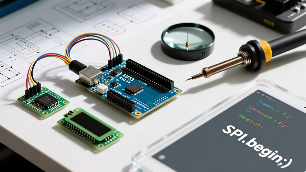
To communicate via SPI, we utilize the built-in <SPI.h> library. Modern best practices dictate using SPI.beginTransaction() and SPI.endTransaction() rather than the older SPI.transfer() standalone method. This prevents clock speed and data mode conflicts if your project uses multiple SPI libraries (e.g., an SD card and a display simultaneously).
#include <SPI.h>

const int csPin = 10; // Chip Select pin

void setup() {
  Serial.begin(115200);
  pinMode(csPin, OUTPUT);
  digitalWrite(csPin, HIGH); // Deselect the peripheral immediately

  SPI.begin(); // Initialize the SPI bus (MOSI, MISO, SCK)
}

void loop() {
  // Define SPI settings: 8MHz, MSB first, SPI Mode 0
  SPISettings mySettings(8000000, MSBFIRST, SPI_MODE0);

  SPI.beginTransaction(mySettings);
  digitalWrite(csPin, LOW); // Wake up the peripheral

  // Send a command byte (e.g., 0x80 to read a register)
  SPI.transfer(0x80);

  // Read the response byte
  byte response = SPI.transfer(0x00);

  digitalWrite(csPin, HIGH); // Put peripheral back to sleep
  SPI.endTransaction();

  Serial.print("Sensor Response: 0x");
  Serial.println(response, HEX);

  delay(1000);
}
For deeper documentation on the core library functions, always consult the Arduino Official SPI Reference.
Understanding SPI Modes (CPOL and CPHA)
Beginners often copy-paste code only to find the sensor returns 0xFF or 0x00 continuously. This is usually a SPI Mode mismatch. SPI defines four modes (0, 1, 2, and 3) based on two parameters:
- CPOL (Clock Polarity): Is the clock line IDLE when HIGH (1) or LOW (0)?
- CPHA (Clock Phase): Is data sampled on the leading (first) edge or trailing (second) edge of the clock pulse?
Most modern sensors, including the BME280 and NRF24L01, use SPI_MODE0 (CPOL=0, CPHA=0), meaning the clock idles LOW and data is sampled on the rising edge. Always check your component's datasheet. If your wiring is perfect but data is garbage, cycle through SPI_MODE1, SPI_MODE2, and SPI_MODE3 in your SPISettings object.
Real-World Troubleshooting Matrix
When your SPI peripheral refuses to respond, use this diagnostic matrix to isolate the failure mode.
| Symptom | Probable Cause | Actionable Fix |
|---|---|---|
Returns 0xFF constantly |
MISO line disconnected, or peripheral is unpowered. | Check 3.3V power rail. Verify MISO continuity with a multimeter. |
Returns 0x00 constantly |
MISO shorted to ground, or CS pin is stuck HIGH. | Ensure CS pin is pulled LOW before SPI.transfer(). |
| Garbage/Random Data | Wrong SPI Mode, or clock speed exceeds peripheral limit. | Drop clock to 1 MHz for testing. Cycle through Modes 0-3. |
| Works alone, fails with SD Card | Floating CS pin on the inactive device. | Add 10kΩ pull-up resistors to all CS pins to prevent ghosting. |
Summary: When to Choose SPI
Use SPI for Arduino when you need maximum throughput (e.g., pushing pixel data to a screen or reading 32-bit ADCs at 100kHz). If you only need to read a slow temperature sensor or connect a simple I2C OLED, stick to I2C to save GPIO pins. But for high-performance DIY electronics, mastering the SPI bus, proper logic-level shifting, and transaction-based coding is a mandatory rite of passage. For practical wiring examples on a popular sensor, review the Adafruit BME280 Guide to see SPI in action.