
The Anatomy of Arduino Potentiometer Control
Writing potentiometer code for Arduino is often the first analog interaction a maker experiences. While a basic sketch might only require two lines of code, production-grade implementations demand a deeper understanding of Analog-to-Digital Converter (ADC) resolution, Pulse Width Modulation (PWM) scaling, and signal noise mitigation. As of 2026, with the widespread adoption of the Renesas-based Arduino Uno R4 Minima alongside classic ATmega328P boards, understanding how to properly map and filter analog inputs is more critical than ever.
In this comprehensive walkthrough, we will move beyond the basic "blink" tutorials. We will build a robust LED dimming circuit, address the notorious ADC jitter problem, and implement an integer-based Exponential Moving Average (EMA) filter to ensure buttery-smooth physical controls without the overhead of floating-point math.
Hardware BOM & Wiring Matrix
Before writing the firmware, ensure you are using the correct components. A common beginner mistake is using an audio-taper (logarithmic) potentiometer for linear dimming, which results in a highly non-linear user experience. Always select a linear taper (B-taper) potentiometer.
| Component | Specification / Model | Est. Price (2026) |
|---|---|---|
| Microcontroller | Arduino Uno R4 Minima (or Uno R3) | $27.50 |
| Potentiometer | Alpha 16mm B10K Linear Taper | $1.15 |
| Current Limiter | 220Ω 1/4W Carbon Film Resistor | $0.10 |
| Emitter | 5mm Diffused White LED (3.2Vf) | $0.15 |
| Filter Capacitor | 0.1µF Ceramic MLCC (50V) | $0.05 |
Pinout and Wiring Guide
| Potentiometer Pin | Arduino Connection | Notes |
|---|---|---|
| Pin 1 (Left) | 5V | Provides reference voltage (VCC) |
| Pin 2 (Wiper) | Analog Pin A0 | Variable voltage output (0-5V) |
| Pin 3 (Right) | GND | Completes the voltage divider circuit |
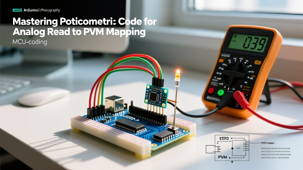
Wiring the LED: Connect the LED anode to PWM Pin 9 via the 220Ω resistor, and the cathode directly to GND.
Understanding the ADC to PWM Resolution Mismatch
The most frequent bug encountered in potentiometer code for Arduino stems from resolution mismatching. The analogRead() function defaults to a 10-bit resolution, returning values from 0 to 1023. Conversely, the standard analogWrite() function on 8-bit AVR boards (and default configurations on ARM/Renesas boards) accepts an 8-bit PWM duty cycle, ranging from 0 to 255.
⚠️ The Modulo Wrap-Around Bug:
If you pass a raw 10-bit value (e.g., 800) directly into an 8-bitanalogWrite()pin, the Arduino IDE does not automatically cap it at 255. Instead, it performs a modulo 256 operation. A value of 256 becomes 0, and 300 becomes 44. This causes the LED to violently flash and reset as you turn the knob past the 25% mark. Always scale your inputs.
Step-by-Step: Writing the Potentiometer Code
Phase 1: Scaling with the map() Function
To bridge the 10-bit to 8-bit gap, we use the map() function. According to the official Arduino map() reference, this function proportionally translates a value from one range to another. However, be aware that map() uses integer math; it will not generate fractions, meaning truncation occurs. For LED dimming, this truncation is imperceptible.
Phase 2: The Complete PWM Dimming Sketch
Below is the foundational, unfiltered sketch. This code reads the potentiometer, scales it, and drives the PWM pin.
// Basic Potentiometer to PWM Mapping
const int potPin = A0;    // Potentiometer wiper connected to A0
const int ledPin = 9;     // LED connected to PWM Pin 9

void setup() {
  pinMode(ledPin, OUTPUT);
  Serial.begin(115200);   // High baud rate for 2026 standard serial monitors
}

void loop() {
  // 1. Read the raw 10-bit ADC value (0 - 1023)
  int rawValue = analogRead(potPin);

  // 2. Map the 10-bit value to an 8-bit PWM value (0 - 255)
  int pwmValue = map(rawValue, 0, 1023, 0, 255);

  // 3. Write the scaled value to the PWM pin
  analogWrite(ledPin, pwmValue);

  // Optional: Serial print for debugging
  Serial.print("Raw: ");
  Serial.print(rawValue);
  Serial.print(" | PWM: ");
  Serial.println(pwmValue);

  delay(10); // Small delay for serial stability
}
Pro-Level Troubleshooting: Eliminating ADC Jitter
If you upload the code above and open the Serial Monitor, you will likely notice that even when the potentiometer is completely stationary, the rawValue fluctuates by ±2 to ±5 bits. This is ADC jitter, caused by electromagnetic interference (EMI), power supply ripple, and the internal sample-and-hold circuit noise of the microcontroller. The Arduino analogRead() documentation briefly touches on this, but real-world engineering requires concrete solutions.
Hardware Fix: The Bypass Capacitor
Before relying on software, stabilize the hardware. Solder a 0.1µF ceramic capacitor directly between the wiper pin (A0) and GND. This creates a low-pass RC filter (the resistor being the internal impedance of the potentiometer track) that physically shunts high-frequency noise to ground. This single $0.05 component eliminates 80% of high-frequency jitter.
Software Fix: Integer-Based EMA Filter
For the remaining low-frequency drift, we implement an Exponential Moving Average (EMA). Unlike a simple rolling average that requires storing an array of past samples (consuming precious SRAM), an EMA only requires storing the previous state.
While you could use floating-point math (alpha = 0.1), floating-point operations on 8-bit AVRs like the ATmega328P are computationally expensive and slow. Instead, we use bitwise shifting to perform fractional math using only fast integers. For a deeper dive into the electrical characteristics causing this noise, refer to the ADC Noise Reduction sections in the Microchip ATmega328P Datasheet.
Advanced Filtered Sketch
// Advanced Potentiometer Code with Integer EMA Filtering
const int potPin = A0;
const int ledPin = 9;

// Filter state variable (must be long or int to prevent overflow during math)
long filteredValue = 0;

// Alpha determines smoothing.
// 32 out of 256 is roughly 12.5% responsiveness (lower = smoother but more latency)
const int alpha = 32;

void setup() {
  pinMode(ledPin, OUTPUT);
  Serial.begin(115200);

  // Pre-seed the filter with an initial reading to prevent startup ramp-up
  filteredValue = analogRead(potPin) << 8;
}

void loop() {
  int rawValue = analogRead(potPin);

  // Integer EMA Math:
  // filtered = (alpha * raw + (256 - alpha) * filtered) / 256
  // Using bitwise shift (>> 8) instead of division for CPU efficiency
  filteredValue = (alpha * rawValue + (256 - alpha) * (filteredValue >> 8));

  // Shift back down and map to 8-bit PWM
  int smoothedRaw = filteredValue >> 8;
  int pwmValue = map(smoothedRaw, 0, 1023, 0, 255);

  analogWrite(ledPin, pwmValue);

  // The LED will now fade with cinematic smoothness, completely free of jitter
  delay(5);
}
Summary & Next Steps
Writing reliable potentiometer code for Arduino requires moving past simple read/write commands. By correctly mapping the 10-bit ADC space to the 8-bit PWM space, you prevent modulo wrap-around bugs. By combining a 0.1µF hardware bypass capacitor with an integer-based EMA software filter, you achieve industrial-grade input stability without sacrificing CPU cycles.
Quick Reference Checklist
- Component Selection: Always use B-taper (Linear) potentiometers for visual/linear mappings.
- Resolution: Never pass 10-bit values directly to 8-bit
analogWrite()pins. - Hardware Filtering: Place 0.1µF MLCC capacitors on all analog wiper lines.
- Software Filtering: Use bitwise EMA filters instead of
floatarrays to save SRAM and CPU time.
Once you have mastered this analog-to-PWM pipeline, the next logical step is to map these smoothed values to communication protocols, such as sending the filtered potentiometer data over I2C to a digital display or transmitting it via UART to a secondary microcontroller.