
The Anatomy of the Quadrature Protocol
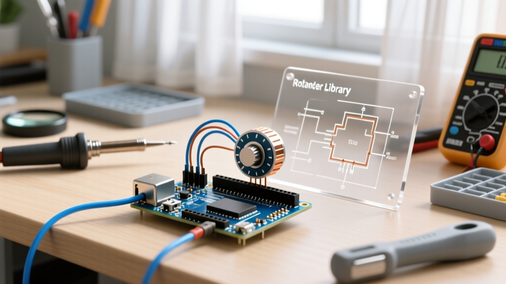
At the heart of modern human-machine interfaces lies the incremental rotary encoder. Whether you are building a CNC jog dial, a digital audio mixer, or a precision robotics joint, relying on raw GPIO polling is a recipe for missed steps and erratic behavior. To achieve flawless tracking, developers rely on a dedicated rotary encoder library for Arduino to abstract the complexities of the underlying quadrature protocol and mechanical switch bounce.
The Quadrature Protocol: A method of encoding rotational direction and speed by reading two square wave signals (Phase A and Phase B) that are mechanically or electronically offset by exactly 90 degrees (one-quarter of a cycle).
When the shaft rotates, the internal contacts (or optical sensors) generate a sequence of HIGH and LOW states. Because Phase A and Phase B are out of phase, the sequence in which they change states dictates the direction of rotation. If Phase A leads Phase B, the encoder is turning clockwise (CW). If Phase B leads Phase A, it is turning counter-clockwise (CCW).
Gray Code State Transitions
Professional libraries do not simply look for a rising edge on a single pin. Instead, they track the 2-bit Gray code state machine. By reading both pins simultaneously, the library can determine the exact vector of movement. Below is the definitive state transition table for a standard 4x decoding algorithm:
| Previous State (A,B) | Current State (A,B) | Binary Transition | Interpreted Direction |
|---|---|---|---|
| 00 | 01 | 00 → 01 | Clockwise (CW) |
| 01 | 11 | 01 → 11 | Clockwise (CW) |
| 11 | 10 | 11 → 10 | Clockwise (CW) |
| 10 | 00 | 10 → 00 | Clockwise (CW) |
| 00 | 10 | 00 → 10 | Counter-Clockwise (CCW) |
| 10 | 11 | 10 → 11 | Counter-Clockwise (CCW) |
| 11 | 01 | 11 → 01 | Counter-Clockwise (CCW) |
| 01 | 00 | 01 → 00 | Counter-Clockwise (CCW) |
A high-quality library utilizes a 16-element lookup array in memory to map the combined previous and current states (4 bits total) to a directional output (-1, 0, or +1). This guarantees O(1) constant time execution inside the interrupt service routine (ISR).
Why Raw Polling Fails: The Case for a Dedicated Library
Beginners often attempt to read encoders using digitalRead() inside the main loop(). This approach fails in real-world applications for two critical reasons:
- Execution Latency: If your main loop takes 15 milliseconds to execute (due to LCD updates, WiFi stack processing, or sensor polling), you will completely miss the 2-millisecond pulse width generated by a fast-spinning encoder.
- Mechanical Contact Bounce: Inexpensive mechanical encoders, like the ubiquitous KY-040 (typically costing around $1.50 to $2.00 in bulk), suffer from severe contact bounce. As the metal wiper slides across the stator contacts, it physically bounces, generating dozens of micro-transitions over a 5ms window. Without state-machine filtering, a single physical detent click will register as 15 chaotic steps forward and backward.
According to the official Arduino Interrupt Documentation, utilizing hardware interrupts (INT0 and INT1 on pins 2 and 3 of the ATmega328P) allows the microcontroller to pause the main program and read the pin states within microseconds. However, writing a bounce-proof ISR from scratch is error-prone, which is why leveraging an established library is the industry standard.
Top Rotary Encoder Libraries for Arduino Compared
Not all libraries are created equal. Some prioritize low memory footprint, while others prioritize multi-core support and hardware timer integration. Here is a comparison of the top three libraries used in 2026:
| Library Name | Author / Maintainer | Decoding Method | Best Use Case | Memory Overhead |
|---|---|---|---|---|
| Encoder | Paul Stoffregen (PJRC) | Interrupt + Polling fallback | High-speed tracking, Teensy/AVR | Medium (~400 bytes) |
| RotaryEncoder | Matthias Hertel | Polling (State Machine) | Low-speed UI dials, ATtiny85 | Low (~150 bytes) |
| Ai Esp32 Rotary | Igor Antolic | Hardware PCNT (Pulse Counter) | ESP32 / ESP32-S3 high-load apps | Negligible (Hardware) |
For standard Arduino Uno or Nano projects, Paul Stoffregen's PJRC Encoder Library remains the gold standard. It intelligently attaches to hardware interrupts if the pins support them, and falls back to highly optimized timer-based polling if they do not. For ESP32 developers dealing with heavy WiFi/BLE stacks, the Ai Esp32 Rotary library offloads the decoding entirely to the ESP32's internal Pulse Counter (PCNT) hardware peripheral, ensuring zero CPU cycles are wasted on GPIO polling.
Hardware Reality: Mechanical Bounce and Electrical Filtering
Even the most brilliantly written rotary encoder library for Arduino cannot fix a degraded electrical signal. If your signal line is ringing due to EMI or capacitance, the microcontroller will read phantom states. To ensure reliable decoding, you must implement proper hardware conditioning.
The RC Low-Pass Filter
For mechanical encoders like the Bourns PEC11R ($3.50 - $5.00 for genuine units) or the generic KY-040, an RC (Resistor-Capacitor) filter is mandatory.
- Resistors: Place 10kΩ pull-up resistors on both the CLK (Phase A) and DT (Phase B) lines to VCC (5V or 3.3V). While the ATmega328P has internal 20kΩ-50kΩ pull-ups, they are often too weak to overcome long wire capacitance.
- Capacitors: Solder a 100nF (0.1µF) X7R ceramic capacitor from the CLK line to GND, and another from the DT line to GND.
The Math: With a 10kΩ resistor and a 100nF capacitor, your RC time constant (τ = R × C) is exactly 1 millisecond. It takes approximately 3τ (3ms) for the capacitor to charge/discharge enough to cross the ATmega328P's logic threshold (approx 2.5V). This effectively masks any mechanical bounce that occurs within a 3ms window, delivering a clean, debounced square wave to the library's ISR.
Edge Cases and Troubleshooting Erratic Steps
When integrating encoders into complex systems, engineers frequently encounter specific failure modes. Here is how to diagnose and resolve them:
1. The 'Double Step' Phenomenon
Symptom: The encoder increments by 2 or 4 for every single physical detent click.
Cause: The library is configured for 4x decoding (counting every edge of both Phase A and Phase B), but the physical encoder only has 1 detent per full quadrature cycle.
Fix: Divide the accumulated library value by 4 in your code, or switch to a 1x decoding library that only triggers on the rising edge of Phase A while sampling Phase B.
2. Erratic Direction Reversals at High Speed
Symptom: Spinning the knob fast results in the value jittering or moving in the wrong direction.
Cause: Signal skew. If the wires for Phase A and Phase B are routed differently, or if one line has more parasitic capacitance, the 90-degree phase shift distorts at high frequencies, causing the state machine to misinterpret the Gray code sequence.
Fix: Keep CLK and DT wires exactly the same length, twist them together to reject common-mode EMI, and use a Schmitt-trigger buffer (like the 74HC14) if cable runs exceed 12 inches.
3. Phantom Interrupts on Power-Up
Symptom: The position variable jumps randomly the moment the Arduino is powered on or reset.
Cause: Floating pins during the microcontroller's boot sequence before pinMode(INPUT_PULLUP) is executed.
Fix: Ensure external 10kΩ pull-up resistors are physically soldered to the encoder module, guaranteeing a stable HIGH state before the MCU initializes its GPIO registers.
Conclusion
Mastering rotary inputs requires looking past the physical knob and understanding the electrical and computational protocols at play. By pairing a robust hardware RC filter with a state-machine-driven rotary encoder library for Arduino, you eliminate contact bounce, prevent missed steps, and achieve the buttery-smooth precision required for professional-grade instrumentation and consumer electronics.