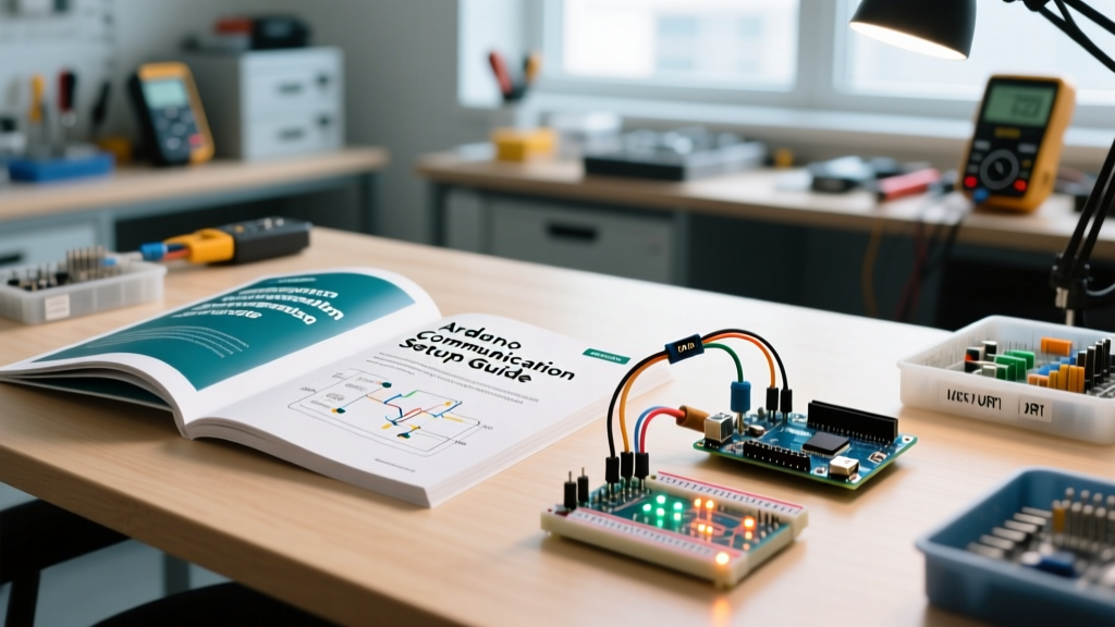

Why Field Engineers Rely on Offline Communication References
When deploying IoT nodes in remote agricultural settings or off-grid weather stations, reliable internet access is a luxury. In these environments, relying on an offline PDF Arduino programming reference manual is not just a convenience; it is a critical necessity for configuring robust communication protocols. While online forums are great for quick fixes, a structured, downloadable PDF Arduino programming guide ensures you have immediate access to datasheets, pinout matrices, and electrical constraints when setting up UART, I2C, and SPI buses in the field.
This guide bridges the gap between theoretical microcontroller datasheets and practical wiring for modern communication setups, focusing on the ESP32-WROOM-32E and legacy ATmega328P architectures.
The Core Communication Matrix
Before soldering wires or writing initialization code, you must select the correct protocol for your payload and distance requirements. The table below serves as a quick-reference matrix typically found in a comprehensive field manual.
| Protocol | Wires Required | Max Speed (Standard) | Max Distance (Practical) | Topology |
|---|---|---|---|---|
| UART | 2 (TX, RX) + GND | 115,200 bps (up to 3 Mbps) | ~15 meters (at 9600 bps) | Point-to-Point |
| I2C | 2 (SDA, SCL) + GND | 400 kHz (Fast Mode) | ~1 meter (highly capacitance-dependent) | Multi-Master/Multi-Slave |
| SPI | 4 (MOSI, MISO, SCK, CS) + GND | 10 MHz - 20 MHz | ~20 cm (without differential drivers) | Master-Slave (Daisy Chain) |
| CAN Bus | 2 (CANH, CANL) + GND | 1 Mbps | Up to 40 meters (at 1 Mbps) | Multi-Master Broadcast |
UART Configuration: ESP32 to Semtech SX1278 LoRa
Long-range communication often relies on LoRa modules like the Semtech SX1278 (typically costing between $5.00 and $8.00 for generic breakout boards). Setting up UART communication between an ESP32-WROOM-32E and an SX1278 requires strict attention to logic levels.
The 3.3V vs 5V Logic Trap
The ESP32 operates strictly at 3.3V logic. The SX1278 is also a 3.3V device. If you are using an ESP32, you can wire the TX and RX pins directly. However, a common failure mode occurs when engineers swap the ESP32 for a 5V Arduino Uno in the field. Never connect a 5V Arduino TX pin directly to a 3.3V LoRa RX pin. The overvoltage will stress the LoRa module's RF front-end, leading to degraded receiver sensitivity and eventual silicon failure.
- Solution: Use a bidirectional logic level shifter based on the BSS138 MOSFET (e.g., the Adafruit 4-channel shifter, approx. $3.95).
- Wiring: Connect LV to 3.3V, HV to 5V, and route the UART lines through the corresponding channels.
Baud Rate and Hardware Serial Selection
For ESP32 Arduino programming, avoid using the default Serial (UART0) for external modules, as it is tied to the onboard USB-to-UART bridge used for flashing and debugging. Instead, utilize Hardware Serial 1 or 2. According to the official Espressif ESP32-WROOM-32E datasheet, UART pins can be mapped to almost any GPIO via the GPIO matrix.
Expert Field Tip: When configuring UART over twisted-pair cables longer than 2 meters, terminate the lines with a 120Ω resistor at the receiver end to prevent signal reflection, and drop the baud rate to 9600 bps to increase the noise margin.
I2C Bus Capacitance and Pull-Up Resistor Math
I2C is notoriously fragile in noisy environments. Many engineers search for a PDF Arduino programming cheat sheet to solve I2C lockups, but true mastery requires understanding the underlying electrical constraints defined in the NXP I2C-bus specification (UM10204).
Calculating the Correct Pull-Up Resistor
I2C lines (SDA and SCL) are open-drain. They require pull-up resistors to return to a HIGH state. The value of these resistors depends on the bus capacitance ($C_b$) and the supply voltage ($V_{cc}$).
The minimum resistor value is dictated by the maximum allowable sink current ($I_{OL}$), typically 3mA for standard microcontrollers:
R_p(min) = (V_cc - V_OL) / I_OL
For a 3.3V system where $V_{OL}$ is 0.4V:
R_p(min) = (3.3 - 0.4) / 0.003 = 966 Ω
Therefore, using a standard 2.2kΩ or 4.7kΩ resistor is safe. However, if you are running I2C over a long ribbon cable, the bus capacitance increases. The I2C spec limits standard mode capacitance to 400pF. If your rise time is too slow due to high capacitance and a 4.7kΩ resistor, the bus will fail. Drop the resistor to 1.0kΩ (ensure your MCU can sink the resulting 3.3mA) or switch to an active I2C bus extender like the PCA9600.
Arduino IDE I2C Optimization
By default, the Arduino Wire library initializes I2C at 100 kHz (Standard Mode). If your sensors support it, force Fast Mode (400 kHz) to reduce the time the bus is occupied, minimizing the window for EMI interference.
Wire.begin();
Wire.setClock(400000); // Set I2C to 400kHz Fast Mode
SPI Timing: Navigating CPOL and CPHA Modes
When setting up high-speed peripherals like SD card modules or TFT displays, SPI is the protocol of choice. The most frequent cause of SPI failure in Arduino programming is a mismatch in Clock Polarity (CPOL) and Clock Phase (CPHA).
- Mode 0 (CPOL=0, CPHA=0): Clock is LOW when idle. Data is sampled on the rising edge. (Most common for SD cards).
- Mode 3 (CPOL=1, CPHA=1): Clock is HIGH when idle. Data is sampled on the rising edge. (Common for certain RF transceivers like the nRF24L01+).
Always consult the peripheral's datasheet. If your SPI.beginTransaction(SPISettings(10000000, MSBFIRST, SPI_MODE0)) yields garbage data, flip to SPI_MODE3 before assuming a wiring fault.
Field Debugging with Logic Analyzers
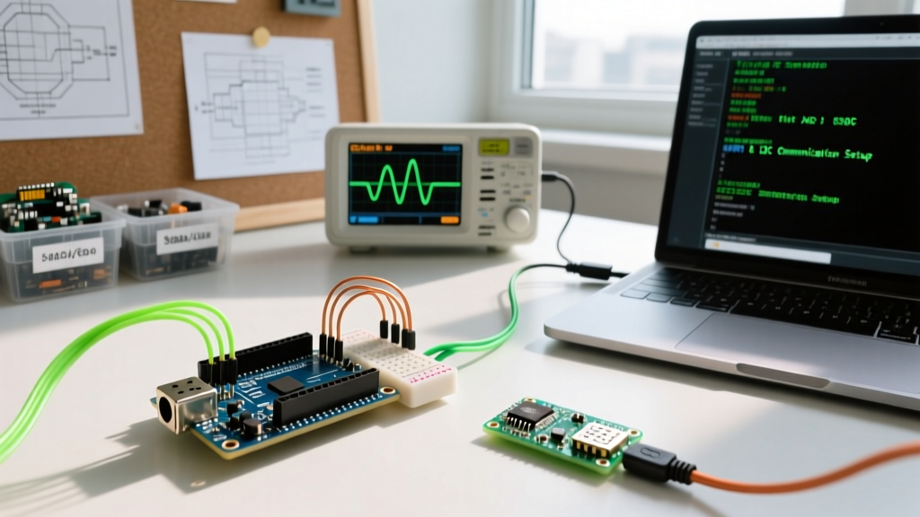
When a communication bus fails, guessing is not an option. A portable USB logic analyzer is an essential component of any field kit. The Saleae Logic 8 (approx. $119.00) or budget alternatives based on the Cypress CY7C68013A chip (approx. $12.00) allow you to decode I2C addresses, UART hex payloads, and SPI clock phase errors in real-time.
When debugging I2C, look for the 9th clock pulse (the ACKnowledge bit). If the SDA line remains HIGH during the 9th pulse, the slave device is either unpowered, wired incorrectly, or responding to the wrong 7-bit address.
Curated Offline PDF Resources for Your Kit
To build your ultimate offline reference library, download and compile the following authoritative documents into a single PDF Arduino programming and hardware manual before heading to a remote deployment site:
- Microcontroller Datasheets: The Espressif ESP32 Technical Reference Manual and the Microchip ATmega328P Datasheet.
- Protocol Specifications: The NXP UM10204 I2C Specification and the SD Association's SPI Mode Physical Layer Simplified Specification.
- Transceiver Manuals: Semtech SX1276/77/78/79 Datasheet for LoRa register mapping and CAD (Channel Activity Detection) configuration.
For foundational software architecture, the official Arduino communication documentation provides excellent baseline examples that can be printed or saved as PDFs via your browser for offline access.
Frequently Asked Questions (FAQ)
Can I use I2C for communication between two separate Arduino boards?
Yes, but it requires careful configuration. One board must be configured as the Master and the other as the Slave using Wire.onRequest() and Wire.onReceive() callbacks. Ensure both boards share a common ground, and if they operate at different logic levels (e.g., a 5V Uno and a 3.3V Pro Mini), a logic level shifter on the SDA and SCL lines is mandatory.
Why does my UART connection drop packets over a 5-meter cable?
Standard CMOS UART signals are unbalanced and highly susceptible to capacitive loading and electromagnetic interference (EMI) over long distances. For runs exceeding 2 meters, use a differential line driver like the MAX485 (RS-485 standard) to convert the UART signals, allowing reliable communication over hundreds of meters using twisted-pair cabling.
How do I find the I2C address of an undocumented sensor module?
Use an I2C scanner script. The standard Arduino I2C Scanner sketch iterates through all 127 possible I2C addresses and listens for an ACKnowledge (ACK) signal. Be aware that some modules use 8-bit addressing in their documentation (which includes the Read/Write bit), while the Arduino Wire library strictly uses 7-bit addressing. If the datasheet says 0xD0, shift it right by one bit (0x68) for your Arduino code.