
The Hidden Complexities of Arduino to Arduino SPI
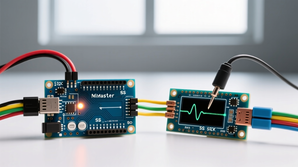
Serial Peripheral Interface (SPI) is the undisputed king of short-distance, high-speed board-to-board communication. While I2C and UART dominate multi-node and long-distance sensor networks, SPI remains the go-to protocol when you need to push megabytes of data between microcontrollers with minimal latency. In 2026, with the Arduino ecosystem spanning legacy 8-bit AVR boards to modern 32-bit ARM Cortex-M4 architectures, establishing a flawless Arduino to Arduino SPI link is more complex than simply copying a legacy tutorial.
Unlike I2C, SPI lacks hardware addressing and built-in acknowledgment packets. It is a raw, synchronous shift-register protocol. When an Arduino to Arduino SPI connection fails, it rarely throws a clean error code; instead, you get silent data corruption, frozen master loops, or unresponsive slaves. This comprehensive error-fix guide dissects the physical, electrical, and software-layer failures that plague SPI implementations and provides exact, actionable solutions.
Diagnostic Matrix: Identifying Your SPI Failure Mode
Before rewriting your firmware, map your symptoms to the most common physical and logical failure modes. Use this diagnostic matrix to isolate the root cause of your communication breakdown.
| Symptom | Probable Cause | Quick Fix / Verification Step |
|---|---|---|
| Master sends data, Slave receives garbage or zeros | Clock Polarity/Phase (CPOL/CPHA) mismatch or crossed MISO/MOSI | Verify SPI_MODE0 through SPI_MODE3 on both boards; swap MISO/MOSI lines. |
Master hangs indefinitely during SPI.transfer() |
Hardware Slave Select (SS) pin floating or pulled LOW on Master | Ensure hardware SS pin is set to OUTPUT on the Master ATmega board. |
| Slave receives data only when logic analyzer is attached | Floating chip select line or missing common ground reference | Connect a dedicated GND wire between both Arduinos; add 10k pull-up on SS. |
| Intermittent corruption at high speeds (e.g., >4MHz) | Parasitic capacitance on long jumper wires or 5V/3.3V logic clash | Shorten wires to <10cm; implement a BSS138 logic level shifter. |
Hardware Pinout Verification Across Architectures
The most frequent point of failure in Arduino to Arduino SPI setups is assuming the SPI header pins are universal. They are not. The physical pins mapped to the SPI peripheral change drastically depending on the microcontroller architecture.
Standard SPI Pin Mapping Table
| Board Model | Microcontroller | MOSI | MISO | SCK | Hardware SS |
|---|---|---|---|---|---|
| Arduino Uno R3 / Nano | ATmega328P (8-bit AVR) | Pin 11 | Pin 12 | Pin 13 | Pin 10 |
| Arduino Mega 2560 | ATmega2560 (8-bit AVR) | Pin 51 | Pin 50 | Pin 52 | Pin 53 |
| Arduino Nano 33 IoT | SAMD21 (32-bit ARM) | Pin 11 | Pin 12 | Pin 13 | Pin 10 |
| Arduino Uno R4 Minima | Renesas RA4M1 (32-bit ARM) | Pin 11 | Pin 12 | Pin 13 | Pin 10 |
Note: While you can use any digital pin as the Chip Select (CS) for your slave device, the "Hardware SS" pin listed above has special electrical significance on 8-bit AVR boards, which leads us to the most notorious SPI trap.
The ATmega "Hardware SS" Trap
If you are using an Arduino Uno, Nano, or Mega as the SPI Master, you must understand a hardware-level quirk of the ATmega SPI peripheral. According to the Nick Gammon SPI Guide, the microcontroller's SPI hardware constantly monitors the state of the dedicated hardware SS pin (Pin 10 on Uno, Pin 53 on Mega).
Critical Rule: If the hardware SS pin is configured as an
INPUTand is drivenLOWby external noise or a connected circuit, the ATmega SPI peripheral will instantly and silently revert to Slave Mode. The Master will stop generating clock signals, and yourSPI.transfer()commands will fail or hang.
The Fix: Even if you are using Pin 9 or Pin 8 as your actual Chip Select line for the slave Arduino, you must include the following line in your Master's setup() function to lock the hardware peripheral into Master mode:
pinMode(10, OUTPUT); // For Uno/Nano
pinMode(53, OUTPUT); // For Mega
Software Configuration: The Death of Clock Dividers
If you are copying code from forums dated prior to 2020, you will likely encounter the SPI.setClockDivider() function. In modern Arduino IDE environments (2.3.x and newer), this legacy approach is deprecated and highly discouraged for multi-device buses.
Using legacy dividers leaves the SPI bus vulnerable to interrupt-driven state corruption. If an interrupt service routine (ISR) triggers mid-transfer and uses a library that alters the SPI bus, your clock speed and bit-order settings will be overwritten.
The Modern SPISettings Standard
To ensure robust, thread-safe Arduino to Arduino SPI communication, you must encapsulate your bus parameters using the SPISettings object. This guarantees that the bus configuration is applied atomically and protected from interrupt interference.
Define your settings globally:
SPISettings mySettings(4000000, MSBFIRST, SPI_MODE0);
Then, wrap every transfer block in transaction guards:
SPI.beginTransaction(mySettings);
digitalWrite(csPin, LOW);
SPI.transfer(dataByte);
digitalWrite(csPin, HIGH);
SPI.endTransaction();
For 8-bit AVR Arduinos (16MHz clock), a 4MHz SPI clock (SPI_CLOCK_DIV4) is the practical maximum for reliable transmission over standard Dupont jumper wires. Pushing to 8MHz (SPI_CLOCK_DIV2) often results in signal ringing and bit-flipping unless you are using a custom PCB with controlled impedance traces.
Advanced Slave Reception: Polling vs. Interrupts
When configuring the receiving Arduino as an SPI Slave, many beginners rely on a while loop polling the SPI Data Register (SPDR). This is a catastrophic design flaw for high-speed transfers. If the Master clocks data at 4MHz, the Slave has exactly 2 microseconds (on a 16MHz AVR) to read the byte before it is overwritten by the next incoming byte.
The Fix: You must use the SPI Serial Transfer Complete interrupt. On ATmega328P boards, this is handled via the SPI_STC_vect interrupt vector. By enabling the SPI interrupt (SPCR |= _BV(SPIE);), the microcontroller will automatically trigger an ISR the microsecond a byte is fully shifted into the register, allowing you to copy it to a volatile ring buffer without dropping packets.
For deeper implementation details on SPI interrupt vectors, refer to the Official Arduino SPI Reference Documentation.
Voltage Domain Mismatches: 5V vs 3.3V Logic
A frequent scenario in modern DIY electronics is connecting a 5V Arduino Uno R3 to a 3.3V Arduino Nano 33 BLE or ESP32. SPI is not a differential bus like RS-485; it relies on single-ended CMOS logic thresholds.
- The Danger: Feeding 5V from the Uno's MOSI or SCK pins directly into the 3.3V GPIO of a Nano 33 BLE will degrade the target microcontroller's silicon over time, leading to eventual thermal failure of the input protection diodes.
- The Cheap Fix ($1.50): Use a BSS138 MOSFET-based bi-directional logic level shifter. These are widely available on breakout boards and handle SPI frequencies up to roughly 2MHz reliably.
- The Pro Fix ($4.00): For 4MHz+ SPI clock speeds, the parasitic capacitance of cheap BSS138 modules will round off your square waves, causing the 3.3V slave to misread the clock edges. Use a dedicated active translator IC like the Texas Instruments TXS0108E or SN74LVC8T245, which feature dedicated edge-rate accelerators capable of handling 10MHz+ SPI buses without signal degradation.
Step-by-Step Logic Analyzer Debugging Workflow
When serial prints fail and multimeters show static voltages, you must visualize the bus. A $15 USB 24MHz 8-channel logic analyzer (compatible with Sigrok/PulseView or Saleae Logic 2) is mandatory for serious SPI debugging.
- Ground First: Connect the logic analyzer GND to the common ground shared by both Arduinos. Never probe SPI without a common ground reference.
- Probe the Big Three: Attach channels to SCK, MOSI, and the Master's CS pin. Leave MISO disconnected initially to reduce capacitive load on the bus while verifying Master transmission.
- Verify Clock Idle State: Trigger a capture. In
SPI_MODE0, the SCK line must idleLOW. If it idlesHIGH, your Master is configured forSPI_MODE2orSPI_MODE3, and the Slave will read data on the wrong clock edge. - Check CS Timing: Ensure the CS line goes
LOWat least 5 microseconds before the first SCK rising edge. ATmega slaves require setup time to wake the SPI peripheral from idle states.
By visually decoding the MOSI line against the SCK edges in your logic analyzer software, you can instantly verify if the Master is transmitting the correct payload, completely isolating the fault to the Slave's hardware or interrupt configuration.
Summary of Best Practices
Successful Arduino to Arduino SPI communication demands respect for the physical layer and strict adherence to modern software transaction guards. Always hardwire your grounds, enforce Master-mode hardware SS pins, utilize SPISettings to protect against interrupt corruption, and never mix 5V and 3.3V logic domains without active translation. For an excellent primer on the underlying shift-register mechanics of the protocol, the SparkFun SPI Tutorial remains an invaluable foundational resource.