
Introduction to 13.56 MHz RFID Protocols in Microcontrollers
Integrating an Arduino and RFID reader into a project requires more than just plugging in jumper wires; it demands a strict understanding of underlying communication protocols. High-Frequency (HF) RFID systems operating at 13.56 MHz, governed by the ISO/IEC 14443A standard, rely on precise digital signaling to negotiate data transfers between the microcontroller and the reader module. Whether you are building a secure door lock, an automated inventory tracker, or a contactless payment terminal, the choice of protocol—specifically Serial Peripheral Interface (SPI) versus Inter-Integrated Circuit (I2C)—dictates your system's speed, wiring complexity, and reliability.
In 2026, the market remains dominated by two primary silicon architectures for hobbyist and prosumer applications: the NXP MFRC522 and the NXP PN532. While both read standard MIFARE Classic and NTAG21x transponders, their protocol implementations and edge-case behaviors differ drastically. This guide dissects the physical and data-link layers of connecting these readers to an Arduino, providing actionable wiring schematics, timing constraints, and protocol-level troubleshooting frameworks.
The Core Contenders: MFRC522 vs PN532 Hardware Comparison
Before diving into the protocol layers, it is critical to select the correct silicon for your application. The MFRC522 is a cost-effective, read-only (for the most part) ISO14443A reader, while the PN532 is a highly versatile NFC controller capable of card emulation and peer-to-peer communication.
| Feature | MFRC522 (RC522 Module) | PN532 (Elechouse v3 Module) |
|---|---|---|
| Average Cost (2026) | $2.50 - $4.00 | $8.50 - $14.00 |
| Primary Interface | SPI (Default) | I2C / SPI / HSU (Switchable) |
| Logic Level | Strict 3.3V (Not 5V tolerant) | 3.3V with onboard level shifters (v3) |
| Tag Emulation | No | Yes (Target Mode) |
| Max Read Range | ~50mm (with standard coil) | ~70mm (with optimized antenna) |
SPI Protocol: Wiring and Timing the MFRC522
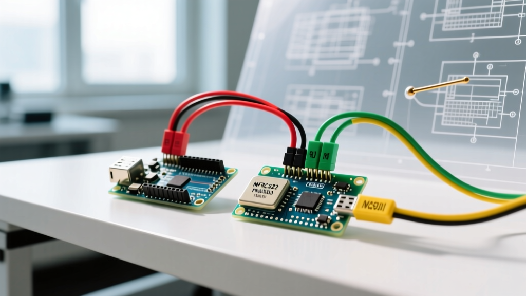
The SPI protocol is a synchronous, full-duplex communication bus. The MFRC522 module defaults to SPI out of the box. When interfacing an Arduino and RFID reader via SPI, the microcontroller acts as the Controller (formerly Master), and the MFRC522 acts as the Peripheral (formerly Slave).
Pinout and Logic Level Translation
A catastrophic failure mode for beginners is connecting the 5V logic pins of an Arduino Uno (ATmega328P) directly to the MFRC522. The MFRC522 datasheet explicitly states a maximum VCC and logic input of 3.6V. Applying 5V to the MOSI, SCK, or CS pins will permanently degrade the silicon. You must use a bidirectional logic level shifter, such as the BSS138 MOSFET-based module or a CD4050B hex buffer.
| MFRC522 Pin | Arduino Uno Pin | Protocol Function |
|---|---|---|
| SDA (SS) | Digital 10 | Chip Select (Active LOW) |
| SCK | Digital 13 | Serial Clock (CPOL=0, CPHA=0) |
| MOSI | Digital 11 | Controller Out, Peripheral In |
| MISO | Digital 12 | Peripheral Out, Controller In |
| IRQ | Not Connected | Interrupt (Optional for polling) |
SPI Timing Constraints and Edge Cases
The MFRC522 supports SPI clock speeds up to 10 MHz. However, when using the standard Arduino SPI.h library alongside long jumper wires (exceeding 15cm), signal integrity degrades due to parasitic capacitance. According to the Arduino SPI Communication Guide, dropping the clock divider to SPI_CLOCK_DIV4 (4 MHz on a 16MHz Uno) resolves 90% of intermittent checksum failures during MIFARE block reads.
Expert Tip: The Chip Select (CS) line must be driven HIGH immediately after a transaction completes. Leaving CS LOW while performing other SPI operations on the same bus (e.g., writing to an SD card) will cause the MFRC522 to interpret unrelated bus traffic as corrupted register commands, leading to a locked state that requires a hard hardware reset via the RST pin.
I2C Protocol: Configuring the PN532 Module
While the PN532 supports SPI, it is most frequently deployed using the I2C protocol in complex Arduino projects to conserve digital I/O pins. I2C is a multi-controller, multi-peripheral half-duplex bus requiring only two wires: SDA (data) and SCL (clock).
Hardware Switching and Pull-Up Resistors
To enable I2C on the popular Elechouse PN532 v3 module, you must physically toggle the onboard DIP switches to the I2C position (typically Switch 1 ON, Switch 2 OFF). The module's I2C address is hardcoded to 0x24 (7-bit address space).
Unlike SPI, I2C relies on open-drain architecture. The PN532 v3 module includes onboard 10kΩ pull-up resistors tied to 3.3V. If your I2C bus wiring exceeds 30cm, or if you have multiple devices on the bus, the 10kΩ resistors may be too weak to pull the line HIGH fast enough, resulting in skewed SDA rise times. In these scenarios, adding external 4.7kΩ or 2.2kΩ pull-up resistors to the 3.3V rail is mandatory to maintain protocol compliance.
SAM Configuration: The Hidden I2C Handshake
A common protocol-level trap when coding the PN532 is failing to initialize the Secure Access Module (SAM). Before the PN532 can generate the 13.56 MHz RF field and poll for tags, the Arduino must send the SAMConfiguration command (0x14) via I2C. If your code immediately attempts to call readPassiveTargetID() without configuring the SAM, the PN532 will return a NACK (Not Acknowledged) or a timeout error. Always structure your setup() function to verify SAM readiness before entering the polling loop.
MIFARE Memory Architecture and Protocol Security
Understanding the physical layer is only half the battle; parsing the data requires knowledge of the ISO14443A memory layout. The standard MIFARE Classic 1K tag, frequently used in legacy access systems, contains 1024 bytes of EEPROM divided into 16 sectors.
- Sectors: 16 total (Sector 0 to 15).
- Blocks: 4 blocks per sector (Block 0 to 3).
- Bytes: 16 bytes per block.
The final block of each sector (Block 3) is the Sector Trailer. It contains two cryptographic keys (Key A and Key B, 6 bytes each) and access control bits. To read or write to Blocks 0-2, the Arduino and RFID reader must first execute an Authentication command using the correct 6-byte key. If authentication fails, the tag silently drops the connection, and the reader returns a generic timeout error.
Security Note for 2026: The Crypto-1 algorithm used by MIFARE Classic has been cryptographically broken for years. For any modern commercial deployment, engineers should utilize the PN532 to read NTAG215 (which uses simple password protection but larger memory) or MIFARE DESFire EV3 tags, which utilize AES-128 encryption and dynamic authentication protocols.
Troubleshooting Protocol Failures and Edge Cases
When your Arduino and RFID reader fail to communicate, the issue is rarely the code logic; it is almost always a physical or protocol-layer violation. Use this diagnostic matrix to isolate the fault:
- MFRC522 Returns '0x00' or '0xFF' for Firmware Version:
- Cause: SPI bus is not initializing, or MISO line is floating.
- Fix: Verify the 3.3V logic level shifter is powered on both the HV and LV sides. Ensure the CS pin is explicitly set to
OUTPUTand drivenHIGHin the first line ofsetup().
- PN532 I2C 'Wire.endTransmission()' Returns Error 2 (NACK on Address):
- Cause: The Arduino is looking for the wrong I2C address, or the DIP switches are incorrect.
- Fix: Run an I2C scanner sketch. The PN532 will show up as
0x24. If it shows as0x48, you are in SPI mode or the module is misconfigured.
- Tag Read is Intermittent or Requires Touching the Antenna:
- Cause: RF field detuning caused by metal proximity or insufficient current delivery.
- Fix: Ensure the RFID reader is mounted at least 15mm away from any ground planes or metal enclosures. The Arduino's onboard 3.3V regulator often maxes out at 150mA; the PN532 can draw up to 120mA during peak RF transmission. Power the reader's VCC directly from an external 3.3V buck converter (e.g., AMS1117-3.3) rather than the Arduino's 3.3V pin.
References and Further Reading
To deepen your understanding of the electrical characteristics and protocol timing diagrams discussed in this guide, consult the following authoritative documentation:
- Arduino Official SPI Communication Guide - Detailed breakdown of clock dividers, bit ordering, and hardware SPI pin mappings across AVR and ARM architectures.
- Arduino Official I2C Communication Guide - Comprehensive overview of pull-up resistor calculations, address spaces, and Wire library limitations.
- NXP MFRC522 Product Data Sheet - The definitive source for SPI timing diagrams, register maps, and absolute maximum ratings for the 13.56 MHz reader IC.