
Beyond the Blink: Why Basic Arduino Code Traffic Light Tutorials Fail
When most beginners search for arduino code traffic light tutorials, they are immediately presented with a flawed paradigm: the blocking delay() function. While sequencing Red, Yellow, and Green LEDs using delay(5000) works for a static desk toy, it completely fails in real-world embedded systems. If your microcontroller is sleeping inside a delay function, it cannot poll pedestrian crossing buttons, read inductive loop sensors, or trigger emergency vehicle preemption (EVP) interrupts.
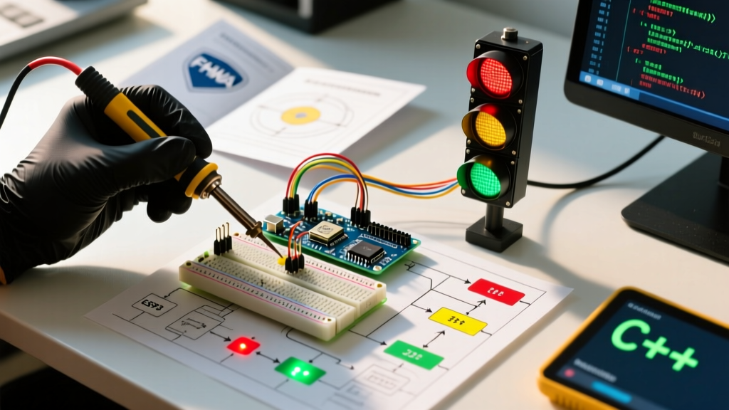
To build a robust, production-grade intersection simulator, we must abandon sequential blocking code and embrace Finite State Machines (FSM) and non-blocking task scheduling. This deep dive explores how to architect professional-grade traffic light logic using advanced C++ libraries and real-world traffic engineering standards.
The FHWA Standard: Real-World Traffic Light Timing
Before writing a single line of code, an embedded systems engineer must understand the domain. Traffic signal timing in the United States is governed by the Federal Highway Administration (FHWA) and detailed in the Traffic Signal Timing Manual. You cannot simply guess the yellow light duration.
Engineering Insight: The yellow clearance interval is calculated based on the 85th-percentile approach speed. For a 35 mph zone, the FHWA recommends a yellow duration of exactly 4.0 seconds, followed by an all-red clearance interval of 1.5 seconds. Hardcoding arbitrary delays like
delay(2000)for yellow violates safety standards and promotes the "dilemma zone" crash phenomenon.
Therefore, our Arduino architecture must allow dynamic timing adjustments based on sensor inputs without halting the main execution loop.
2026 Hardware BOM and GPIO Limitations
Driving high-visibility traffic light modules requires more than plugging LEDs directly into an ATmega328P. Let us review a professional Bill of Materials (BOM) for a single 3-aspect intersection mast arm, keeping in mind the strict current limitations of the microcontroller.
| Component | Specific Model / Value | Estimated Cost (2026) | Engineering Purpose |
|---|---|---|---|
| Microcontroller | Elegoo Uno R3 (ATmega328P-PU) | $13.50 | Main logic controller, 5V logic level. |
| LED Driver IC | Texas Instruments ULN2003A | $0.85 | Darlington array to sink current for 12V LED modules. |
| Red LED Module | Kingbright WP113SRD (Super Bright) | $0.45 | Stop aspect. Vf = 1.85V, If = 20mA. |
| Yellow LED Module | Kingbright WP113SYD (Super Bright) | $0.45 | Caution aspect. Vf = 2.0V, If = 20mA. |
| Green LED Module | Kingbright WP113ZGD (Super Bright) | $0.60 | Go aspect. Vf = 3.3V, If = 20mA. |
| Pedestrian Button | Carling V-Series Pushbutton (IP68) | $8.20 | Weatherproof crosswalk request input. |
Critical Failure Mode - GPIO Overcurrent: According to the Microchip ATmega328P Datasheet, the absolute maximum DC current per I/O pin is 40mA, but the recommended continuous operating current is 20mA. If you attempt to wire three high-power 12V intersection LEDs directly to the Arduino GPIO pins, you will instantly fry the silicon die. Always use the ULN2003A or a logic-level MOSFET (like the IRLZ44N) to switch high-current loads.
Library Deep Dive: TaskScheduler vs. Custom FSM
To manage the complex timing of an intersection, we evaluate two dominant library approaches in the Arduino ecosystem.
1. Arkhipenko's TaskScheduler
The TaskScheduler library is a cooperative multitasking framework. It allows you to define tasks (e.g., "Check Pedestrian Button", "Poll Ambient Light Sensor", "Update LED States") and assign them independent intervals. The scheduler's execute() method runs in the main loop(), invoking callbacks only when their specific time intervals expire. This is ideal for sensor polling but can become unwieldy when managing the strict sequential logic of a 4-way intersection.
2. Custom C++ Finite State Machine (FSM)
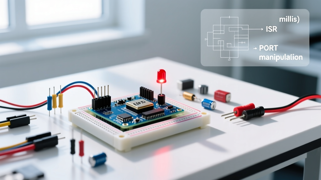
For the actual light sequencing, a custom FSM class is superior. An FSM explicitly defines states (RED, RED_YELLOW, GREEN, YELLOW) and the exact conditions required to transition between them. By combining a custom FSM with the millis() function (as demonstrated in the official Arduino BlinkWithoutDelay documentation), we achieve perfectly non-blocking state transitions.
Implementing the Non-Blocking Arduino Code Traffic Light
Below is the architectural blueprint for implementing a non-blocking FSM for a single intersection approach. We avoid the delay() function entirely.
- Define the Enum States: Create an
enumforSTATE_RED,STATE_GREEN,STATE_YELLOW, andSTATE_PEDESTRIAN_WALK. - Track Time Dynamically: Use
unsigned long previousMillis = 0;andunsigned long interval = 5000;to track how long the system has been in the current state. - The Transition Logic: Inside the
loop(), calculatecurrentMillis - previousMillis. If it exceeds theinterval, trigger the state transition function. - Handle Interrupts: Attach an interrupt to the pedestrian button pin (e.g., Pin 2). When triggered, it sets a boolean flag
pedestrianRequest = true. The FSM checks this flag during theSTATE_GREENevaluation to decide whether to extend the green light or transition to yellow.
This architecture ensures that even if the green light interval is set to 45 seconds, a pedestrian button press is registered within microseconds, and the system gracefully queues the crosswalk sequence without resetting the entire intersection.
Edge Cases: Brownouts, Bouncing, and Burnouts
Writing robust arduino code traffic light logic requires anticipating hardware failures that basic tutorials ignore.
Switch Bouncing in Pedestrian Crosswalks
Mechanical pushbuttons suffer from contact bounce, generating dozens of false HIGH/LOW transitions over a 5-millisecond window when pressed. If your interrupt service routine (ISR) increments a counter or triggers a state change on every edge, a single pedestrian press might request the crosswalk 40 times. Solution: Implement a software debounce lockout inside the ISR using millis(), or use a hardware RC low-pass filter (10kΩ resistor + 0.1µF ceramic capacitor) paired with a 74HC14 Schmitt trigger.
LED Burnout Detection
In real municipal traffic cabinets, a burned-out red bulb triggers a "Conflict Monitor Unit" (CMU) to instantly flash all intersection lights as a 4-way stop. You can simulate this on an Arduino by placing a low-value shunt resistor (e.g., 1Ω) in series with the LED ground path. By reading the voltage drop across the shunt resistor using the ATmega328P's 10-bit ADC (analogRead()), the code can detect if the current drops to zero, indicating a blown LED, and trigger a safe-fail state.
Brown-Out Detection (BOD)
When driving inductive loads or long cable runs to LED mast arms, voltage sags can cause the ATmega328P to enter an undefined state, potentially turning all lights green simultaneously—a fatal failure mode. Ensure the BOD fuse is enabled in the Arduino bootloader (typically set to 2.7V or 4.3V). If VCC drops below this threshold, the BOD circuitry forces a hardware reset, keeping the GPIO pins in a high-impedance (safe) state until power stabilizes.
Comparison Matrix: Execution Methods
| Method | CPU Blocking? | Scalability | Best Use Case |
|---|---|---|---|
delay() |
Yes | Poor | Simple blink tests, debugging. |
millis() (Manual) |
No | Moderate | 2-3 concurrent timers, basic FSMs. |
| TaskScheduler Library | No | Excellent | Sensor polling, telemetry, watchdogs. |
| Custom C++ FSM Class | No | Excellent | Strict sequential logic (Traffic lights). |
Conclusion
Transitioning from a basic blinking script to a professional-grade intersection controller requires a shift in how you perceive time and state within the microcontroller. By leveraging non-blocking libraries, adhering to FHWA timing standards, and designing for hardware edge cases like contact bounce and brownouts, your arduino code traffic light project evolves from a classroom exercise into a robust, real-world embedded system.