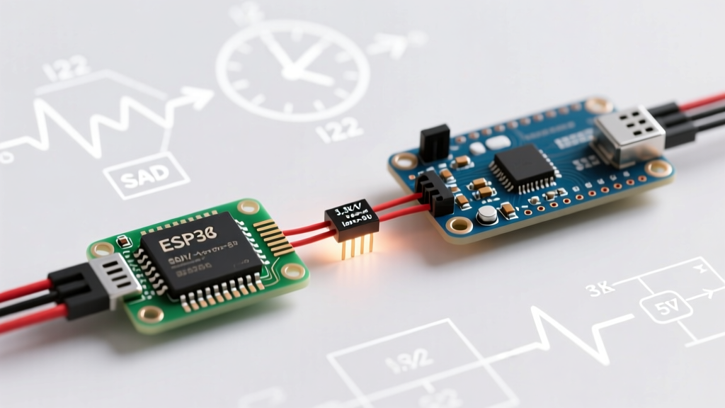

The Anatomy of I2C Arduino to Arduino Communication
Connecting two microcontrollers via the Inter-Integrated Circuit (I2C) bus is a cornerstone of embedded systems design. While UART is simpler for point-to-point text streams, I2C allows for structured, multi-node data exchange using only two wires: SDA (data) and SCL (clock). However, executing reliable I2C Arduino to Arduino communication requires moving beyond basic tutorials and understanding the physics of the bus and the internals of the native Wire library.
In 2026, the standard Arduino ecosystem heavily features mixed-voltage environments. Pairing a classic 5V Arduino Uno R4 Minima ($27.50) with a 3.3V Arduino Nano ESP32 ($21.00) is incredibly common for edge-computing IoT projects. This guide provides a deep dive into the hardware prerequisites, buffer limitations, and advanced error handling required to make your I2C link bulletproof.
Terminology Update: Following industry-wide updates by the MIPI Alliance and NXP, the I2C specification has officially deprecated the terms "Master" and "Slave." In modern Arduino documentation and the latest Wire library updates, these are now referred to as Controller (initiates clock/transfers) and Target (responds to requests). We will use this modern terminology throughout this guide.
Hardware Prerequisites & The Level-Shifting Matrix
The most frequent cause of failed I2C Arduino to Arduino projects is a logic level mismatch. Driving a 3.3V Target's SDA/SCL pins with 5V logic from a Controller will degrade the ESP32 or SAMD silicon over time, eventually causing permanent GPIO failure.
While resistor voltage dividers are often suggested in beginner forums, they are fundamentally flawed for I2C. I2C is an open-drain bus; devices pull the line LOW, but rely on external pull-up resistors to pull the line HIGH. A passive voltage divider introduces massive RC delay, destroying the signal integrity at Fast Mode (400 kHz) speeds.
The BSS138 MOSFET Solution
The industry standard for bidirectional I2C level shifting is the BSS138 N-channel MOSFET circuit, available on breakout boards from Adafruit or SparkFun for roughly $2.95. It safely translates 5V to 3.3V without introducing the capacitance bottlenecks of resistor dividers.
| Controller (5V Uno R4) | BSS138 Level Shifter | Target (3.3V Nano ESP32) | Notes & Pull-Ups |
|---|---|---|---|
| 5V Pin | LV (Low Voltage Side) VCC | 3.3V Pin | Powers the respective sides of the MOSFET gates. |
| GND | GND (Both Sides) | GND | Critical: A common ground is mandatory for I2C reference. |
| A4 (SDA) | LV1 | A4 (SDA) | Ensure 4.7kΩ pull-up to 3.3V on the HV side. |
| A5 (SCL) | LV2 | A5 (SCL) | Ensure 4.7kΩ pull-up to 3.3V on the HV side. |
According to the NXP I2C-bus specification (UM10204), the bus capacitance must not exceed 400 pF. Long wires and cheap level shifters add parasitic capacitance. If your bus fails at 400 kHz, drop the clock speed to 100 kHz using Wire.setClock(100000); in your setup function.
Deep Dive: The Native Wire.h Library
The native Wire library is a wrapper around the hardware Two-Wire Interface (TWI) peripheral found on AVR, SAMD, and ESP32 silicon. While the official Arduino Wire Reference covers basic byte transmission, it rarely discusses the underlying buffer constraints that cause silent data truncation.
Overcoming the 32-Byte Buffer Bottleneck
On standard AVR-based boards (like the Uno R3 or Mega 2560), the Wire library allocates a strictly limited 32-byte hardware buffer. If you attempt to send an array or struct larger than 32 bytes in a single Wire.write() transaction, the excess data is silently discarded. Modern boards like the Nano ESP32 or Zero feature 128-byte or 256-byte buffers, but writing cross-compatible code requires respecting the lowest common denominator.
To transmit complex telemetry (e.g., GPS coordinates, IMU quaternions) from a Target to a Controller, avoid sending strings. Instead, use C++ unions or struct casting to pack binary data efficiently.
// Target (Transmitter) Code Snippet
struct Telemetry {
  float temperature;
  float humidity;
  uint16_t battery_mv;
};

Telemetry sensorData;

void requestEvent() {
  sensorData.temperature = 22.5;
  sensorData.humidity = 45.2;
  sensorData.battery_mv = 3850;

  // Cast struct to byte pointer for raw I2C transmission
  Wire.write((byte*)&sensorData, sizeof(sensorData));
}
On the Controller side, you read the exact number of bytes into a matching struct. This reduces a 25-byte ASCII string payload down to a 10-byte binary payload, keeping you well within the 32-byte AVR safety limit and drastically reducing bus occupancy time.
Advanced Error Handling: Timeouts and NACKs
A major edge case in I2C Arduino to Arduino communication is clock stretching or a Target freezing mid-transaction. If the Target holds the SCL line LOW indefinitely, the Controller's Wire library will hang the entire microcontroller in an infinite while loop waiting for the bus to clear.
Implementing setWireTimeout()
To prevent catastrophic system lockups in production firmware, you must implement hardware timeouts. Introduced in recent versions of the Arduino core, setWireTimeout() allows the TWI peripheral to abort a transaction if the Target fails to respond.
void setup() {
  Wire.begin();
  // Set timeout to 25,000 microseconds (25ms)
  // The 'true' flag resets the bus automatically upon timeout
  Wire.setWireTimeout(25000, true);
}
When utilizing timeouts, you must rigorously check the return value of Wire.endTransmission(). The library returns specific diagnostic codes that are invaluable for debugging:
- 0: Success. Data transmitted and ACKnowledged.
- 1: Data too long to fit in the transmit buffer (truncation occurred).
- 2: Received NACK on transmit of address (Target is disconnected or wrong address).
- 3: Received NACK on transmit of data (Target rejected the payload).
- 4: Other error (bus collision or hardware fault).
- 5: Timeout (Target held SCL low or failed to respond in time).
Pull-Up Resistor Physics: Why Internal Pull-Ups Fail
Many developers attempt to save BOM costs by enabling the microcontroller's internal pull-up resistors via pinMode(SDA, INPUT_PULLUP). This is a critical mistake for any I2C bus spanning more than a few inches.
Internal AVR pull-ups are typically between 20kΩ and 50kΩ. According to Texas Instruments Application Note SLVA689, the pull-up resistor value is dictated by the bus capacitance and the required rise time. A 50kΩ resistor combined with 100pF of cable capacitance results in an RC rise time that violates the I2C specification's maximum rise time limits at 400 kHz, leading to corrupted bytes and phantom NACKs.
Actionable Rule: Always use external 4.7kΩ resistors tied to the logic-level VCC (3.3V or 5V) for Standard Mode (100 kHz). If operating at Fast Mode (400 kHz) or Fast Mode Plus (1 MHz), drop the pull-ups to 2.2kΩ or 1kΩ respectively to ensure sharp signal edges.
Real-World Debugging Workflow
When your I2C Arduino to Arduino link fails, avoid blindly rewriting code. Follow this hardware-first diagnostic sequence:
- Run an I2C Scanner: Upload Nick Gammon's classic I2C Scanner sketch to the Controller. If the Target's address (e.g., 0x08) does not appear, you have a physical layer issue (wiring, power, or blown GPIO).
- Check Common Ground: Use a multimeter to verify continuity between the GND pins of both Arduinos. A missing common ground causes the SDA/SCL signals to float outside the receiver's common-mode voltage range.
- Measure Idle Voltage: With the bus idle, measure SDA and SCL with a multimeter. Both should read exactly VCC (3.3V or 5V). If they read 1.5V or float, your pull-up resistors are missing or broken.
- Inspect Address Shifting: Remember that the Arduino
Wirelibrary uses 7-bit addressing. If your Target logic analyzer shows 0x10 on the bus, the Arduino code must request address 0x08 (the 7-bit value shifted right by one).
Summary
Mastering I2C Arduino to Arduino communication requires respecting the electrical realities of the open-drain bus and the software constraints of the Wire library. By utilizing proper BSS138 level shifters, packing binary structs to avoid buffer overruns, and implementing hardware timeouts, you can build multi-microcontroller architectures that survive real-world noise and edge-case failures.