
The Evolution of Arduino SPI Communication
When working with high-speed peripherals like TFT displays, SD cards, or external flash memory, the Serial Peripheral Interface (SPI) remains the undisputed workhorse of embedded systems. However, as of 2026, with the proliferation of multi-core microcontrollers like the RP2350 and ESP32-S3 running alongside legacy 8-bit AVRs, bus contention and data corruption have become increasingly common. Many developers still rely on outdated tutorials that misuse the SPI library Arduino environment provides, leading to erratic behavior when multiple devices share the same bus.
This guide bypasses the basic blink-style tutorials and dives deep into professional code patterns, hardware-level optimizations, and structural best practices for mastering SPI communication in your embedded projects.
The Golden Rule: Always Use SPI Transactions
The most critical mistake developers make is using legacy SPI configuration functions like SPI.setClockDivider() or SPI.setDataMode(). In a modern ecosystem where an SPI bus might host an SD card (requiring 400 kHz during initialization and 25 MHz for data transfer) and a BME280 sensor (requiring 10 MHz), global settings will inevitably cause one device to fail.
The modern Arduino SPI Reference mandates the use of the Transaction API. This pattern encapsulates the bus configuration, ensuring that interrupts or RTOS tasks cannot hijack the SPI settings mid-transfer.
The Safe Transaction Code Pattern
Below is the definitive boilerplate for any SPI device driver you write. It guarantees that the bus is locked, configured, utilized, and released atomically.
#include <SPI.h>

// Define device-specific SPISettings globally or in a class
// BME280: 10MHz, MSB first, Mode 0
SPISettings bmeSettings(10000000, MSBFIRST, SPI_MODE0);

const int BME_CS = 10;

void setup() {
  SPI.begin();
  pinMode(BME_CS, OUTPUT);
  digitalWrite(BME_CS, HIGH); // Deselect device initially
}

uint8_t readBME280Register(uint8_t reg) {
  uint8_t result;

  // 1. Acquire the bus and apply settings
  SPI.beginTransaction(bmeSettings);

  // 2. Assert Chip Select (Active LOW)
  digitalWrite(BME_CS, LOW);

  // 3. Perform the transfer
  SPI.transfer(reg | 0x80); // Set MSB for read operation
  result = SPI.transfer(0x00); // Clock in the data

  // 4. Deassert Chip Select
  digitalWrite(BME_CS, HIGH);

  // 5. Release the bus
  SPI.endTransaction();

  return result;
}
Expert Insight: Never callSPI.begin()inside a transaction or a loop. It initializes the hardware peripheral and should only be called once insetup(). Calling it repeatedly can reset the SPI state machine on AVR and SAMD architectures, causing clock line glitches.
Demystifying SPI Modes (CPOL and CPHA)
A frequent source of silent failures is mismatched SPI modes. The Analog Devices SPI Introduction outlines how Clock Polarity (CPOL) and Clock Phase (CPHA) dictate the timing of data sampling. Using the wrong mode will result in shifted bits or completely garbled data.
| SPI Mode | CPOL (Idle Clock) | CPHA (Sampling Edge) | Common Example ICs |
|---|---|---|---|
| Mode 0 | LOW (0) | Leading (Rising) | BME280, W25Q128 Flash, SD Cards, MAX7219 |
| Mode 1 | LOW (0) | Trailing (Falling) | MAX31855 (Thermocouple), some older ADCs |
| Mode 2 | HIGH (1) | Leading (Falling) | LSM6DS3 (Accelerometer - alternate mode) |
| Mode 3 | HIGH (1) | Trailing (Rising) | MAX31855 (Alternate), ENC28J60 Ethernet |
Debugging Tip: If your MISO data looks like it is shifted by exactly one bit, or if the first bit is consistently dropped, you are almost certainly using the wrong CPHA setting. Swap between Mode 0 and Mode 1 (or 2 and 3) to resolve this.
Chip Select (CS) Optimization: Beyond digitalWrite()
When pushing SPI clocks past 10 MHz, the overhead of the Arduino digitalWrite() function becomes a severe bottleneck. On a 16 MHz ATmega328P, digitalWrite() takes roughly 3.5 microseconds. If you are toggling the CS pin for every byte in a 4KB SD card sector write, you are wasting over 14 milliseconds of CPU time—time that could be spent processing sensor fusion algorithms.
The Direct Port Manipulation Pattern
For AVR-based boards (Uno, Nano, Mega), bypass the Arduino abstraction layer and manipulate the hardware registers directly. This reduces the CS toggle time to 62.5 nanoseconds.
// Example for Arduino Uno Pin 10 (PORTB, Bit 2)
#define CS_LOW()  (PORTB &= ~(1 << PB2))
#define CS_HIGH() (PORTB |= (1 << PB2))

void fastTransfer() {
  SPI.beginTransaction(mySettings);
  CS_LOW();
  SPI.transfer(0xAA);
  CS_HIGH();
  SPI.endTransaction();
}
For 32-bit ARM Cortex-M boards (Teensy 4.1, STM32, RP2040), use the manufacturer's hardware abstraction or the digitalWriteFast library, which compiles down to single-cycle instructions when the pin number is a constant.
Signal Integrity and Hardware Debugging at High Speeds
Writing perfect code is only half the battle. According to the SparkFun SPI Tutorial, physical wiring limitations often masquerade as software bugs. When operating at 24 MHz or higher, SPI traces act as transmission lines.
Hardware Best Practices Checklist
- Series Termination Resistors: Place 33Ω to 47Ω resistors in series on the MOSI and SCK lines, as close to the master MCU as possible. This dampens high-frequency ringing and prevents signal reflection.
- Ground Return Paths: Ensure there is a solid ground plane or multiple ground wires connecting the master and slave. A floating ground between an ESP32 and an SD card module will cause intermittent CRC failures.
- Level Shifting Capacitance: If using a bi-directional logic level shifter (like the BSS138 MOSFET design) for 5V/3.3V translation, be aware that the parasitic capacitance can destroy signal edges above 8 MHz. For high-speed SPI, use dedicated ICs like the TXB0104 or SN74LVC1T45.
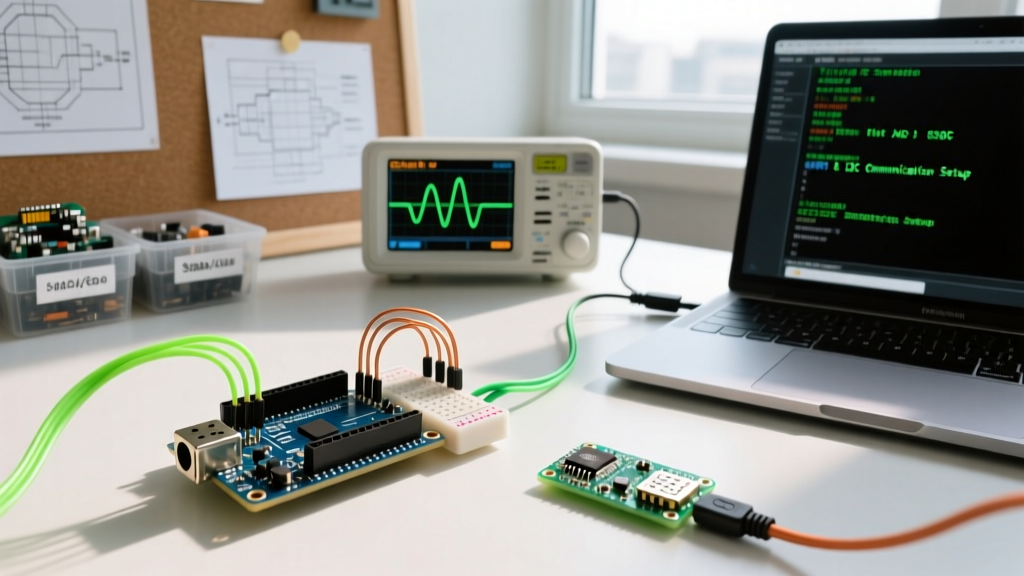
- Logic Analysis: Stop guessing. Use a tool like the Saleae Logic Pro 8 (or a budget 24MHz 8-channel clone) to capture the SCK, MOSI, MISO, and CS lines simultaneously. Set the trigger to the falling edge of CS to isolate exact transaction failures.
Advanced Pattern: Non-Blocking DMA Transfers
As embedded applications in 2026 demand more real-time processing, blocking the CPU during an SPI transfer is unacceptable. Direct Memory Access (DMA) allows the SPI peripheral to move data directly to RAM without CPU intervention.
While the standard Arduino SPI.h library abstracts DMA away, advanced users on platforms like the Teensy or STM32 can utilize asynchronous transfer functions. The pattern involves setting up a double-buffer: while the DMA transmits Buffer A, the CPU processes Buffer B.
// Pseudo-code concept for DMA Double Buffering
volatile bool dma_busy = false;

void dmaCompleteCallback() {
  dma_busy = false; // Interrupt fires when transfer finishes
}

void loop() {
  if (!dma_busy) {
    // Swap buffers and start next transfer
    SPI.transfer(out_buffer, in_buffer, BUFFER_SIZE, dmaCompleteCallback);
    dma_busy = true;

    // CPU is now free to process the PREVIOUS buffer's data
    processSensorData(previous_in_buffer);
  }

  // Run other critical tasks here
  updateMotorPID();
}
Summary of Best Practices
Mastering the SPI library Arduino ecosystem provides requires moving beyond simple byte transfers. By strictly adhering to the Transaction API, matching CPOL/CPHA modes to your specific silicon, optimizing Chip Select toggling via direct port manipulation, and respecting high-speed signal integrity, you will eliminate the vast majority of communication errors in your projects. Always verify your physical layer with a logic analyzer before rewriting your firmware.