
Core Architecture: How the Arduino Serial Monitor Works
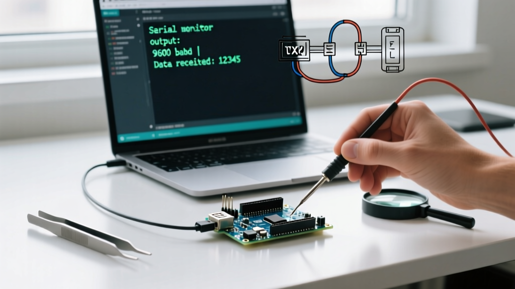
The Arduino Serial Monitor is the primary graphical interface for UART (Universal Asynchronous Receiver-Transmitter) communication within the Arduino IDE. While it appears as a simple text console, it acts as the host-side endpoint for your microcontroller's hardware serial buffers. Understanding the underlying USB-to-Serial bridge is critical for effective debugging in 2026, especially as the ecosystem has diversified far beyond the classic ATmega328P.
USB-to-Serial Bridge Comparison
Not all boards handle serial connections identically. The behavior of the Serial Monitor—specifically regarding auto-reset and native USB enumeration—depends entirely on the bridge IC or native USB peripheral.
| Bridge IC / Architecture | Common Boards | Auto-Reset on Serial Open? | Baud Rate Enforcement |
|---|---|---|---|
| ATmega16U2 (Dedicated Bridge) | Uno R3, Mega 2560 | Yes (via DTR line & 0.1µF capacitor) | Strict (Hardware UART limits) |
| CH340G / CH341A | Uno R3 Clones, Nano Clones | Yes (via DTR line) | Strict (Max ~230,400 bps reliably) |
| CP2102 / CP2104 | NodeMCU, ESP8266 Dev Boards | Yes (via DTR/RTS boot mode logic) | Strict (Hardware UART limits) |
| Native USB (Hardware USB PHY) | Leonardo, Zero, ESP32-S3, RP2040 | No (Virtual COM port, no DTR reset) | Ignored (USB is packet-based, not baud-bound) |
Expert Insight: If you are using a native USB board like the Arduino Leonardo or ESP32-S3, the baud rate you specify inSerial.begin(115200)is essentially ignored by the hardware. The USB link operates at full USB 2.0 Full-Speed (12 Mbps) or High-Speed (480 Mbps). The baud rate parameter only matters if you are communicating with an external hardware UART peripheral (like a GPS module) usingSerial1.
Step-by-Step Arduino Serial Monitor Setup in IDE 2.x
With the widespread adoption of Arduino IDE 2.3.x, the Serial Monitor has transitioned from a pop-up window to a dockable, multi-tabbed panel. This allows you to monitor multiple COM ports simultaneously—a massive workflow improvement for multi-MCU projects.
1. Initialization and Port Binding
Before opening the monitor, your sketch must initialize the serial buffer. The standard initialization allocates a 64-byte RX and TX buffer in SRAM.
void setup() {
  // Initialize serial communication at 115200 bits per second
  Serial.begin(115200);

  // Optional: Wait for serial port to connect (Native USB boards only)
  while (!Serial) {
    delay(10);
  }
  Serial.println("System Boot Complete.");
}
2. Configuring the IDE 2.x Interface
- Target Port: Ensure the dropdown in the top-right of the Serial Monitor panel matches your active upload port (e.g.,
COM3or/dev/ttyACM0). - Baud Rate Selector: Must exactly match the integer passed to
Serial.begin(). Mismatches result in mojibake (garbled text). - Line Ending Dropdown: Crucial for bidirectional communication. Options include No line ending, Newline (\n), Carriage return (\r), and Both NL & CR (\r\n).
- Timestamp Toggle: Injects a millisecond-precision local timestamp before every received line. Invaluable for profiling loop execution times.
Baud Rate Selection: Speed vs. Reliability Matrix
Selecting the correct baud rate is a trade-off between throughput and signal integrity, especially when using long physical UART wires rather than the onboard USB bridge. According to SparkFun's Serial Communication Guide, higher baud rates drastically reduce the maximum reliable cable length due to capacitive loading and signal degradation.
| Baud Rate (bps) | Bit Duration (µs) | Max Reliable Cable Length (Unshielded) | Primary Use Case |
|---|---|---|---|
| 9600 | 104.1 µs | ~15 meters (50 ft) | Legacy sensors, long-distance RS-485, low-power MCUs |
| 38400 | 26.0 µs | ~5 meters (16 ft) | Standard GPS modules (NMEA sentences) |
| 115200 | 8.68 µs | ~2 meters (6.5 ft) | Standard IDE debugging, ESP32/ESP8266 boot logs |
| 921600 | 1.08 µs | < 0.5 meters (Direct PCB trace) | High-speed data logging, audio streaming buffers |
Advanced Debugging & Data Parsing Techniques
The most common failure mode for beginners using the Arduino Serial Monitor for bidirectional control (e.g., sending motor speed commands from the PC to the MCU) is improper handling of line endings. The official Arduino Serial Reference details how functions like Serial.parseInt() behave, but edge cases often cause silent failures.
The "Line Ending" Trap
If your Serial Monitor is set to Both NL & CR, sending the number 255 actually transmits the ASCII string "255\r\n". If you use Serial.parseInt(), it reads 255, but leaves the \r\n in the buffer. On the next loop iteration, parseInt() times out and returns 0, causing erratic hardware behavior.
Robust Parsing Implementation
Instead of relying on parseInt(), use readStringUntil() combined with explicit string-to-integer conversion to flush the buffer cleanly.
void loop() {
  if (Serial.available() > 0) {
    // Read until the newline character, discarding the rest of the line ending
    String input = Serial.readStringUntil('\n');

    // Trim whitespace and carriage returns
    input.trim();

    if (input.length() > 0) {
      int motorSpeed = input.toInt();
      // Constrain to valid PWM range
      motorSpeed = constrain(motorSpeed, 0, 255);
      analogWrite(9, motorSpeed);
      Serial.print("PWM Set: ");
      Serial.println(motorSpeed);
    }
  }
}
Troubleshooting Common UART and Serial Monitor Failures
1. "Port Busy" or "Access Denied" During Upload
The Problem: You click "Upload" and the IDE throws a ser_open(): can't open device "\\.\COM3": Access is denied error.
The Cause: The Serial Monitor holds an exclusive lock on the COM port. While IDE 2.x attempts to auto-close the monitor during compilation, third-party terminals (like PuTTY or Tera Term) or a frozen IDE background process will block the bootloader from taking over.
The Fix: Manually close the Serial Monitor tab. If the port remains locked, open Windows Device Manager, disable and re-enable the COM port, or physically disconnect and reconnect the USB cable to force the host OS to drop the file handle.
2. The "Clone Board" Driver Conflict (CH340)
Genuine Arduino boards use signed CDC-ACM drivers that Windows and macOS install automatically. Sub-$15 clone boards typically use the WCH CH340G chip. In late 2024 and into 2026, Windows Update occasionally overwrites the functional WCH driver with a generic, incompatible Microsoft serial driver, resulting in the board showing up as an "Unknown USB Device".
The Fix: Download the official CH341SER.EXE installer from the WCH website, run it, and manually force the driver update via Device Manager by selecting "Let me pick from a list of available drivers" and pointing to the WCH folder.
3. Garbled Boot Logs on ESP32
The Problem: The first 2-3 lines of an ESP32 boot sequence look like random symbols (e.g., ets Jul 29 2019... �), while the rest of the Serial Monitor output is perfectly readable at 115200.
The Cause: The ESP32 ROM bootloader outputs its initial hardware diagnostic logs at 74880 bps, a highly non-standard baud rate dictated by the 40MHz crystal oscillator math. Once the Arduino core takes over, it switches the UART to your configured 115200 bps.
The Fix: Ignore the first few lines, or use a hardware logic analyzer (like the $120 Saleae Logic 8 or a $15 FX2LP-based clone) to capture the raw UART TX pin and decode it using dual-baud-rate settings in PulseView or Sigrok.
Summary: Best Practices for 2026
The Arduino Serial Monitor remains the most accessible tool for MCU debugging, provided you respect the underlying hardware constraints. Always match your baud rates, account for native USB enumeration delays, and sanitize your incoming serial buffers against rogue carriage returns. For high-throughput data visualization, remember that the Serial Monitor is text-bound; leverage the Serial Plotter for CSV-formatted telemetry, or migrate to dedicated logging software like CoolTerm when handling binary hex dumps.