
The Anatomy of Arduino Uno Power
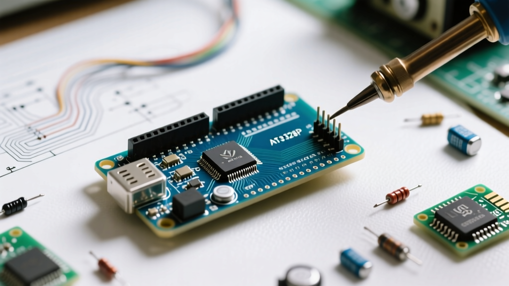
When you first unbox an Arduino Uno Rev3, the immediate instinct is to plug it into a wall adapter or a laptop and start uploading code. However, misunderstanding how to deliver electricity to this board is the number one cause of permanent hardware failure for beginners. Powering the Arduino Uno correctly requires understanding the pathways current takes from the source to the ATmega328P microcontroller.
The ATmega328P microcontroller operates strictly at 5V (with an absolute maximum rating of 6V). If you feed it anything higher, you will instantly destroy the silicon. To protect against this, the Uno features multiple power input methods, each with its own protection circuitry, voltage regulators, and current limits. In this guide, we will break down the exact electrical specifications, thermal limitations, and best practices for every power path on the board.
Expert Insight: Never assume all 5V sources are equal. A USB port, a 9V battery, and a lab bench power supply all interact with the Uno's onboard circuitry in vastly different ways. Choosing the wrong path for high-current peripherals will result in thermal shutdown or a melted voltage regulator.
Path 1: USB Power (The Safest Route)
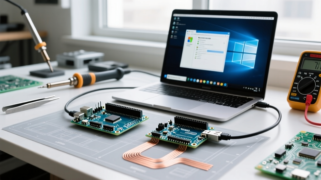
The most common way to power the board is via the USB Type-B connector. This method is highly recommended for beginners because it includes built-in hardware protection against short circuits and overcurrent conditions.
The USB Polyfuse Explained
Between the USB connector and the board's 5V rail sits a resettable PTC (Positive Temperature Coefficient) polyfuse. On the Uno Rev3, this component is typically marked with a '501' or '500' designation. It is designed to trip and cut off power if the current draw exceeds 500mA. Once the short circuit is removed and the component cools down, it resets automatically. This makes USB the most forgiving power source for prototyping.
- Voltage Input: 5V DC (regulated by your computer's USB host or wall brick).
- Current Limit: 500mA (USB 2.0 standard) up to 900mA (USB 3.0 standard), but the onboard polyfuse hard-limits the board draw to ~500mA to protect the host PC.
- Best Use Case: Programming, testing logic circuits, and powering low-draw sensors (I2C, SPI).
Path 2: The Barrel Jack & Linear Regulation
The 2.1mm center-positive barrel jack is designed for standalone operation without a computer. According to the official Arduino Uno Rev3 Documentation, the recommended input voltage for this jack is 7V to 12V, with an absolute maximum limit of 20V (though exceeding 12V is highly discouraged).
The NCP1117 Voltage Regulator and Thermal Math
When you plug a 9V or 12V adapter into the barrel jack, the current passes through a reverse-polarity protection diode and then into an NCP1117ST50T3G linear voltage regulator. This component steps the voltage down to a clean 5V. However, linear regulators do not 'convert' power efficiently; they burn off the excess voltage as heat.
Understanding how voltage regulators dissipate heat is critical. The power dissipated as heat is calculated as:
P(dissipated) = (V_in - 5V) x I_load
Real-World Thermal Scenario
Suppose you power the Uno with a 12V wall adapter and your circuit (sensors, LEDs, shields) draws 150mA (0.15A) from the 5V rail.
- Voltage Drop: 12V - 5V = 7V.
- Power Dissipated: 7V x 0.15A = 1.05 Watts.
- The NCP1117 in a SOT-223 package has a junction-to-ambient thermal resistance of roughly 100°C/W.
- Temperature Rise: 1.05W x 100°C/W = 105°C above ambient.
If your room is 25°C, the regulator's internal junction hits 130°C. It will be too hot to touch, and you are dangerously close to the 150°C thermal shutdown threshold. If you add a motor shield that pulls 300mA, the regulator will thermally shut off, resetting your Arduino randomly.
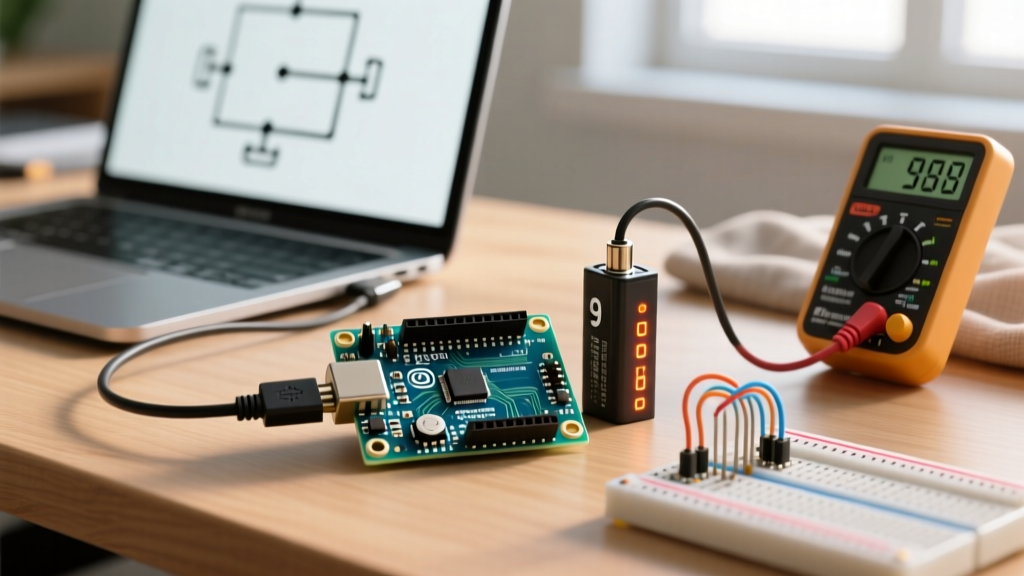
⚠️ Critical Warning: Never use a 9V alkaline smoke-alarm battery for high-current projects. While 9V is within the safe voltage range, standard alkaline 9V batteries have a very high internal resistance and low capacity (approx. 400mAh). They will sag below the 6.1V dropout voltage of the regulator within minutes, causing the Uno to brown-out and reset.Path 3: Direct Pin Injection (The Danger Zone)
The Uno exposes two pins that beginners frequently misuse: the 5V pin and the Vin pin. Bypassing the barrel jack and USB connector removes all safety nets.
The 5V Pin
This pin connects directly to the 5V rail of the board, completely bypassing the NCP1117 regulator and the USB polyfuse. If you connect a 5V power supply here, it works perfectly. However, if you accidentally supply 6V, 9V, or 12V to this pin, you will instantly fry the ATmega328P and the ATmega16U2 USB-to-serial chip. There is no protection.
The Vin Pin
The Vin (Voltage In) pin connects to the input side of the NCP1117 regulator. It is subject to the same thermal limitations as the barrel jack (7V-12V recommended). However, unlike the barrel jack, the Vin pin lacks the reverse polarity protection diode. If you wire a battery backward to the Vin and GND pins, you will destroy the board.
Power Source Comparison Matrix
| Power Method | Input Voltage Range | Max Safe Current (5V Rail) | Protection Features | Best Application |
|---|---|---|---|---|
| USB Type-B | 5V DC | ~500mA | Resettable PTC Polyfuse | Programming, low-power sensors |
| Barrel Jack | 7V - 12V DC | ~150mA (at 12V) ~400mA (at 7V) |
Reverse polarity diode, Thermal shutdown | Standalone projects, moderate loads |
| 5V Pin | 5V DC (Strict) | Depends on external supply | None (Direct to 5V rail) | Custom regulated power supplies |
| Vin Pin | 7V - 12V DC | Same as Barrel Jack | Thermal shutdown only (No polarity protection) | Battery packs (with correct wiring) |
Powering External Peripherals: The Servo & Motor Problem
A common beginner mistake is attempting to power high-draw actuators directly from the Uno's 5V pin. A standard SG90 micro servo draws roughly 10mA at idle but can spike to 250mA - 350mA when stalling. If you plug two servos into the Uno's 5V rail and power the board via USB, the combined 500mA+ draw will trip the USB polyfuse, cutting power to the entire system.
If you power the board via a 12V barrel jack and draw 400mA for servos from the 5V pin, the NCP1117 regulator will dissipate nearly 3 Watts of heat, instantly triggering thermal shutdown and potentially melting the solder joints on the SOT-223 package.
The Professional Solution: External Buck Converters
For any project involving motors, servos, or high-power LED strips, you must decouple the logic power from the actuator power. Purchase an LM2596 step-down buck converter module (typically costing between $2.00 and $4.00).
- Power the Uno via the barrel jack using a 9V or 12V adapter.
- Connect the raw 9V/12V from the adapter to the input terminals of the LM2596 module.
- Use a multimeter to adjust the LM2596's potentiometer until the output reads exactly 5.0V.
- Connect the LM2596's 5V output directly to your servos/motors.
- Crucial Step: Connect the Ground (GND) of the LM2596 to a GND pin on the Arduino Uno. Without a common ground, the Uno's 5V logic signals will not be able to control the external components.
Troubleshooting Common Power Failure Modes
- Symptom: The 'ON' LED is lit, but the board resets when a sensor is triggered.
Diagnosis: Brown-out. Your power supply cannot deliver enough peak current, causing the 5V rail to dip below 4.5V. Upgrade your wall adapter's amperage rating. - Symptom: The NCP1117 regulator is too hot to touch, and the board randomly freezes.
Diagnosis: Thermal shutdown. You are drawing too much current through the barrel jack at a high voltage (e.g., 12V). Lower the input voltage to 7V or use an external buck converter. - Symptom: The board is completely dead, and the USB chip gets instantly hot when plugged in.
Diagnosis: Fatal overvoltage. You likely fed more than 5V into the '5V' pin, destroying the ATmega16U2 and ATmega328P. The board must be replaced.
Summary
Mastering the nuances of powering the Arduino Uno separates hobbyists from reliable engineers. Stick to USB for safe prototyping, respect the thermal limits of the onboard linear regulator when using the barrel jack, and always offload high-current peripherals to dedicated switching regulators. By respecting the electrical boundaries of the ATmega328P and the NCP1117, your boards will survive years of rigorous testing and deployment.