
The Enduring Benchmark of Compact Microcontrollers
Since its initial release, the Arduino Nano has maintained its status as the gold standard for compact, breadboard-friendly prototyping. Measuring exactly 0.73 x 1.70 inches (18 x 45 mm), it packs the core functionality of the Arduino Uno into a fraction of the footprint. However, as projects grow in complexity, understanding the exact Arduino Nano specifications transitions from a casual reference to a critical engineering requirement. In 2026, while newer 32-bit architectures dominate high-performance IoT, the classic 8-bit Nano remains heavily utilized in industrial control panels, custom MIDI controllers, and low-cost sensor arrays due to its predictable timing and massive legacy codebase.
This deep dive dissects the hardware-level realities of the Nano, moving beyond basic marketing specs to explore thermal limitations, timer conflicts, and silicon-level edge cases that frequently trap intermediate developers.
Core Processing and Memory Architecture
The classic Arduino Nano is built around the Microchip (formerly Atmel) ATmega328P microcontroller, operating at a strict 16 MHz clock speed driven by an external surface-mount crystal oscillator. This external clock ensures high timing accuracy, keeping millis() drift to less than 0.1% over 24 hours, which is vital for RTC-less data logging.
Memory Constraints and Bootloader Overhead
Memory management on an 8-bit AVR requires precise allocation. The ATmega328P features a Harvard architecture, separating program memory (Flash) from data memory (SRAM and EEPROM).
| Memory Type | Total Capacity | Available for User Code | Hardware Notes & Constraints |
|---|---|---|---|
| Flash (Program) | 32 KB | 31.5 KB | 512 bytes reserved for the Optiboot bootloader (v8.0+). |
| SRAM (Volatile) | 2 KB | ~1.8 KB | Global variables and the C-stack consume this. Stack overflows cause silent reboots. |
| EEPROM (Non-Volatile) | 1 KB | 1 KB | Rated for 100,000 write cycles. Use wear-leveling for frequent logging. |
Note: When compiling heavy libraries like U8g2 for OLED displays or ArduinoJson, SRAM exhaustion is the most common failure mode. The compiler will warn you if SRAM usage exceeds 75%, but dynamic memory allocation (using String objects) can still fragment the heap and crash the board at runtime.
Power Delivery: Thermal Limits and Voltage Tolerances
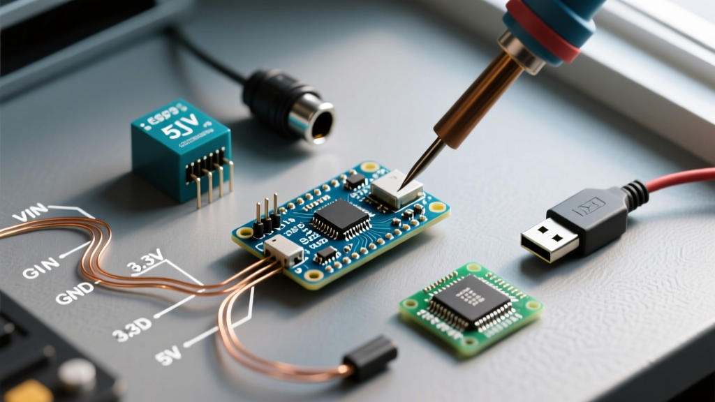
One of the most misunderstood Arduino Nano specifications is its power delivery envelope. The board operates at 5V logic but accepts an unregulated input via the VIN pin or the USB port.
The Linear Regulator Thermal Trap
The Nano utilizes an onboard linear voltage regulator (typically an AMS1117-5.0 or NCP1117ST50T3G depending on the manufacturing batch) to drop VIN down to 5V. Because it is a linear regulator, excess voltage is dissipated as heat. The power dissipation formula is:
P_d = (V_in - 5V) × I_load
If you power the Nano via VIN with a 12V wall adapter and draw 150mA to power a small sensor array and a backlight, the regulator must dissipate 1.05 Watts. The SOT-223 package on the Nano PCB lacks a dedicated thermal via array or heatsink. According to the official Arduino Nano documentation, the recommended input voltage is 7-12V, but pushing 12V with a 150mA load will cause the regulator's junction temperature to exceed 125°C, triggering internal thermal shutdown and causing erratic brownouts.
Expert Power Rule: If your project draws more than 100mA total from the 5V rail, do not use the VIN pin with a source higher than 7.5V. For higher voltages, use an external buck converter (like an LM2596 or MP1584EN module) to step the voltage down to 5V before feeding it into the Nano's 5V pin, entirely bypassing the onboard linear regulator.
Pinout Mapping and Peripheral Allocation
The Nano exposes 30 pins, but not all I/O pins are created equal. Understanding the underlying AVR timer mappings is crucial for avoiding peripheral conflicts.
- Digital I/O Pins: 22 (D0-D13, A0-A7). Note that D0 (RX) and D1 (TX) are shared with the hardware UART and USB-serial bridge. Using them for standard GPIO will break serial communication and interfere with the bootloader handshake.
- PWM Channels: 6 pins (D3, D5, D6, D9, D10, D11). These are tied to specific hardware timers:
- Timer0 (8-bit): D5, D6. Warning: Timer0 is hardcoded to handle
millis(),delay(), andmicros(). Altering its prescaler viaanalogWrite()frequency modifications will break all timing functions. - Timer1 (16-bit): D9, D10. Used by the standard
Servo.hlibrary. Attaching servos to these pins disables PWM functionality on them. - Timer2 (8-bit): D3, D11. Safe for custom high-frequency PWM generation (e.g., 31.25 kHz for motor control to avoid audible whine).
- Timer0 (8-bit): D5, D6. Warning: Timer0 is hardcoded to handle
- Analog Inputs: 8 channels (A0-A7). Critical Edge Case: Pins A6 and A7 are strictly analog inputs on the ATmega328P TQFP-32 package. They lack internal digital pull-up/pull-down resistors and cannot be used with
digitalRead()ordigitalWrite(). Attempting to do so will yield unpredictable floating values. - Communication Interfaces:
- I2C: A4 (SDA), A5 (SCL). Lacks dedicated hardware pull-ups on the Nano PCB; external 4.7kΩ resistors are mandatory for bus lengths over 10cm.
- SPI: D11 (MOSI), D12 (MISO), D13 (SCK). Note on D13: This pin is tied to the onboard status LED via an op-amp buffer (on Rev3 boards) or a direct 1kΩ resistor (older revisions). This adds capacitance that can corrupt high-speed SPI data lines if not accounted for in trace routing.
USB-to-Serial Interfaces: FT232RL vs. CH340G/C
The official Arduino Nano (priced around $24.50 in 2026) historically utilized the FTDI FT232RL USB-to-serial bridge. This chip is highly reliable, supports advanced baud rates, and has native OS support. However, due to supply chain costs, the vast majority of third-party clone boards (typically $3.50 to $5.00) use the WCH CH340G or CH340C chips.
As of 2026, the CH340C (which includes an integrated crystal oscillator, improving EMI performance over the older CH340G) is natively supported by Windows 11 and macOS Sonoma without manual driver installation. However, if you are deploying Nanos in industrial environments using locked-down Linux kiosks or older Windows 10 LTSC builds, you must manually provision the WCH V3.8 drivers, or the board will fail to enumerate on the COM port.
Real-World Failure Modes and Debugging
1. Brown-Out Detection (BOD) Resets
The ATmega328P features a hardware Brown-Out Detection circuit. By default, the Arduino bootloader sets the BOD fuse to trigger a reset if VCC drops below 2.7V. If you attempt to power a Nano directly from a 3.3V LDO or a pair of AA batteries (3.0V nominal), any transient current spike (like transmitting via an NRF24L01 module) will cause a voltage sag below 2.7V, instantly resetting the microcontroller. To fix this, you must either use a 5V boost converter or re-flash the bootloader with the BOD disabled or set to 1.8V using an ISP programmer.
2. The 'Bootloader Loop' on Manual Reset
When the Nano powers on or receives a DTR (Data Terminal Ready) signal from the USB-serial chip, it enters the Optiboot bootloader for approximately 500ms to check for incoming firmware. If your circuit is pulling the RX pin (D0) low during boot, the bootloader will misinterpret this as a continuous stream of incoming data, trapping the Nano in an infinite bootloader loop. Always ensure D0 has a 10kΩ pull-up resistor if connected to external peripherals.
Frequently Asked Questions (FAQ)
Can the Arduino Nano output 3.3V logic?
The classic Nano operates strictly at 5V logic. Feeding 5V signals into a 3.3V sensor (like the BME280 or modern ESP-01 modules) will destroy the sensor's I/O pins. You must use a bidirectional logic level converter (like the BSS138 MOSFET-based modules) or a voltage divider for the TX/RX lines. If native 3.3V logic is required, upgrade to the Arduino Nano 33 IoT or the Raspberry Pi Pico.
What is the maximum current per I/O pin?
The absolute maximum rating per I/O pin on the ATmega328P is 40mA, but the recommended continuous operating limit is 20mA. Furthermore, the total current sourced or sunk across all VCC and GND pins combined must not exceed 200mA. Driving relays or high-power LEDs directly from Nano pins will degrade the silicon and eventually fry the internal bonding wires.
Does the Nano support hardware interrupts?
Yes, but only on two pins: D2 (INT0) and D3 (INT1). While Pin Change Interrupts (PCINT) can be enabled on almost all other pins via direct register manipulation, they share interrupt vectors by port (PORTB, PORTC, PORTD), requiring software polling to determine which specific pin triggered the event.