
The High-Stakes Reality of Medical Electronics Repair
When a consumer audio amplifier fails, the result is silence. When diagnostic hardware fails, the consequences can be fatal. Troubleshooting medical electronic components requires a fundamental paradigm shift from standard consumer electronics repair. You are not merely restoring functionality; you are guaranteeing patient safety under strict regulatory frameworks like IEC 60601-1. As of 2026, with the proliferation of wearable telemetry and high-density bedside monitors, component-level debugging demands an intimate understanding of galvanic isolation barriers, micro-current leakage limits, and precision analog front-ends (AFEs).
This guide provides a deep-dive technical framework for biomedical equipment technicians (BMETs) and advanced electronics engineers tasked with diagnosing faults in ECG machines, pulse oximeters, and multi-parameter patient monitors.
CRITICAL SAFETY DIRECTIVE: Never bypass isolation barriers or defeat ground-fault protection circuits during bench testing. Under IEC 60601-1 standards, Patient Leakage Current (PLC) must remain below 10 µA in Normal Conditions (NC) and 50 µA in Single Fault Conditions (SFC) for Type BF/CF applied parts. Any component replacement must match or exceed the original dielectric withstand voltage ratings.
Common Failure Modes in Diagnostic Hardware
Medical devices operate in harsh electromagnetic environments, often sharing power grids with high-draw imaging equipment (like MRI or CT scanners) that generate massive transient spikes. Below is a matrix of the most frequent component-level failures encountered in diagnostic gear.
| Component Category | Specific Example | Primary Failure Mode | Clinical Symptom |
|---|---|---|---|
| Isolated DC-DC Converters | RECOM REM3 Series | Internal dielectric breakdown due to thermal cycling | High leakage current alarms; chassis shock hazard |
| Optical Isolators | Vishay VO615A | LED aging causing Current Transfer Ratio (CTR) degradation | Intermittent I2C/SPI bus CRC errors; telemetry dropouts |
| Analog Front-End (AFE) | TI AFE4490 | Input stage ESD latch-up or internal reference drift | Flatline SpO2 readings; high baseline noise on ECG |
| Precision Resistors | Vishay Z-Foil (0.05% Tol) | Thermomechanical stress altering resistance value | Gain errors in instrumentation amplifiers; inaccurate vitals |
Step-by-Step Troubleshooting Workflow
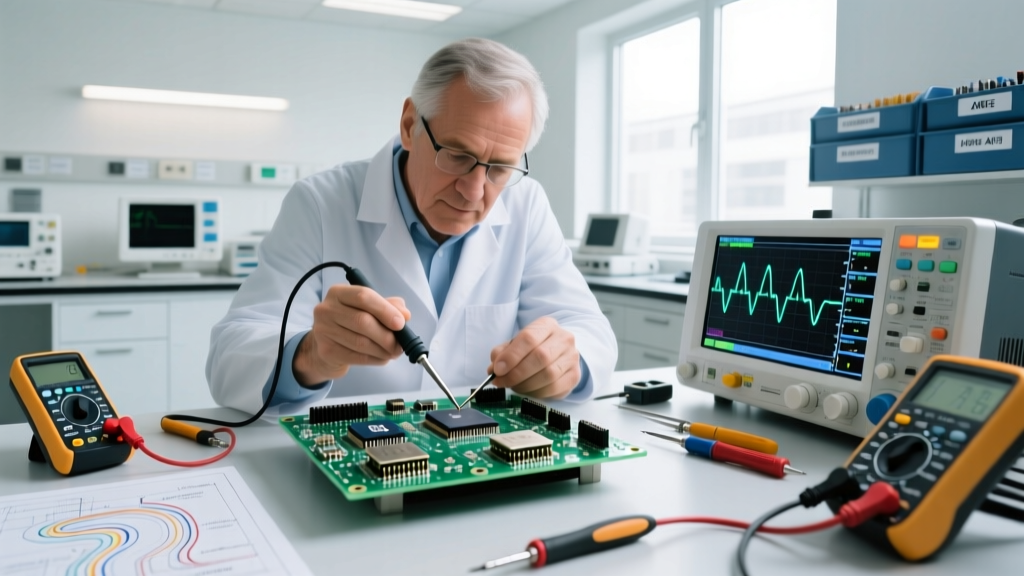
Approaching a faulty patient monitor or ECG machine requires a systematic isolation of the power, digital, and analog domains. Follow this sequence to prevent misdiagnosis and ensure post-repair safety compliance.
Step 1: Electrical Safety Analyzer Baseline Testing
Before opening the chassis, connect the device to an electrical safety analyzer like the Fluke ESA620. Run an automated IEC 60601-1 sequence to measure Earth Leakage, Enclosure Leakage, and Patient Leakage currents. If Patient Leakage exceeds 10 µA before any teardown, you have an immediate isolation failure, likely in the primary-to-secondary power supply or the patient cable itself.
Step 2: Power Supply and Galvanic Isolation Verification
Medical power supplies utilize reinforced isolation. If the safety analyzer flags a leakage fault, isolate the DC-DC converter stage. Medical-grade isolated modules, such as the RECOM REM3 series, feature 4kVDC/1min isolation ratings.
- The Hi-Pot Test: Use a calibrated dielectric withstand tester to apply 4kVDC between the primary input pins and secondary output pins of the isolated DC-DC module. A leakage current reading above 5 µA during this test indicates internal capacitor or transformer insulation breakdown.
- Edge Case: Look for flux residue or conductive dust bridging the 8mm creepage/clearance gap on the PCB beneath the DC-DC module. In 2026, many conformal coating failures are traced back to micro-fractures in the coating caused by automated optical inspection (AOI) handling.
Step 3: Analog Front-End (AFE) Signal Injection
If power and isolation are verified, but the device yields noisy or flatlined physiological data, the fault lies in the AFE. For pulse oximetry, the Texas Instruments AFE4490 is an industry-standard integrated front-end.
- Check the LED Driver Output: Use an oscilloscope to probe the LED driver pins (LED1/LED2). You should see precise, high-current pulses (up to 100mA) timed to the sampling frequency. A flatline here indicates a blown internal current mirror or an open trace on the flexible printed circuit (FPC) connecting to the sensor.
- Verify the Transimpedance Amplifier (TIA): Inject a known, calibrated micro-current signal (e.g., 50 nA AC at 1 kHz) into the photodiode input pins. If the ADC output registers zero or saturates, the internal TIA feedback capacitor has likely failed, or the ESD protection diodes on the input pins have shorted to ground due to a cable defibrillation event.
Deep Dive: Optocoupler CTR Degradation in Telemetry
One of the most insidious, hard-to-troubleshoot failures in medical telemetry packs is optocoupler degradation. Optocouplers (like the Vishay VO615A) are used to pass digital data across the patient isolation barrier. Over 5 to 7 years of continuous operation, the internal infrared LED loses luminous efficiency.
The Current Transfer Ratio (CTR)—the ratio of output transistor current to input LED current—can drop by 40% or more. The digital logic on the secondary side begins to misinterpret logic '1's as '0's, resulting in cyclic redundancy check (CRC) failures on isolated SPI buses.
Diagnostic Fix: Do not just measure continuity. Inject a 5mA test current into the optocoupler anode and measure the collector current on the output side. If the CTR has fallen below the minimum threshold specified in the microcontroller's datasheet (usually 50% for medical-grade designs), replace the optocoupler. Always use medical-grade, high-CTR variants rated for long-term reliability.
Essential Test Equipment Matrix for BMETs
Standard multimeters are insufficient for medical component diagnostics. The following matrix outlines the specialized test equipment required for accurate, compliant troubleshooting in 2026.
| Equipment Type | Recommended Model | Key Parameter Measured | Approx. Cost (2026) |
|---|---|---|---|
| Electrical Safety Analyzer | Fluke ESA620 | Patient Leakage (down to 1 µA) | $6,500 - $7,200 |
| Micro-Ohmmeter | Fluke 8846A (6.5 digit) | Protective Earth (PE) impedance | $1,300 - $1,500 |
| High-Voltage Insulation Tester | Fluke 1587 FC | Dielectric withstand (up to 1kV) | $700 - $850 |
| Patient Simulator | Fluke ProSim 8 | ECG/SpO2/NIBP signal injection | $8,000 - $9,500 |
Post-Repair Validation and Documentation
Replacing a faulty medical electronic component is only half the battle. Once the soldering is complete and the chassis is reassembled, you must perform a full electrical safety re-certification. Document the Earth Leakage, Enclosure Leakage, and Patient Leakage currents. Furthermore, connect a patient simulator (like the Fluke ProSim 8) to verify that the repaired AFE accurately translates simulated physiological waveforms into digital data without introducing baseline wander or 50/60Hz mains hum.
By combining strict adherence to IEC 60601-1 safety limits with component-level signal analysis, you ensure that the diagnostic equipment you service remains both clinically accurate and electrically safe for the most vulnerable users.