
The Anatomy of Component Failure
Diagnosing electronic components defects requires a systematic approach that bridges visual inspection with precise electrical measurement. Whether you are repairing a vintage audio amplifier, performing failure analysis on a modern IoT PCB, or conducting QA on a production line, understanding the physical and electrical signatures of degradation is essential. This cheat sheet provides a high-density reference for identifying faults in passives, semiconductors, and integrated circuits, updated with 2026 diagnostic methodologies and tooling.
The Defect Identification Matrix
| Component Type | Visual Defect Signature | Electrical Symptom | Primary Root Cause |
|---|---|---|---|
| Electrolytic Capacitor | Bulging vent, leaked electrolyte, shrunk sleeve | High ESR, reduced capacitance, ripple noise | Thermal aging, electrolyte evaporation |
| MLCC (Ceramic) | Microscopic edge cracks, chipped terminals | Intermittent short, leakage current, thermal runaway | PCB flexure, mechanical stress, piezoelectric effect |
| Metal Film Resistor | Intact exterior (hidden defect), burnt coating | Open circuit (infinite resistance) | Pulse overload, transient voltage spikes |
| Power MOSFET | Cracked package, melted solder joints | Drain-Source short, Gate leakage | Avalanche breakdown, Gate overvoltage |
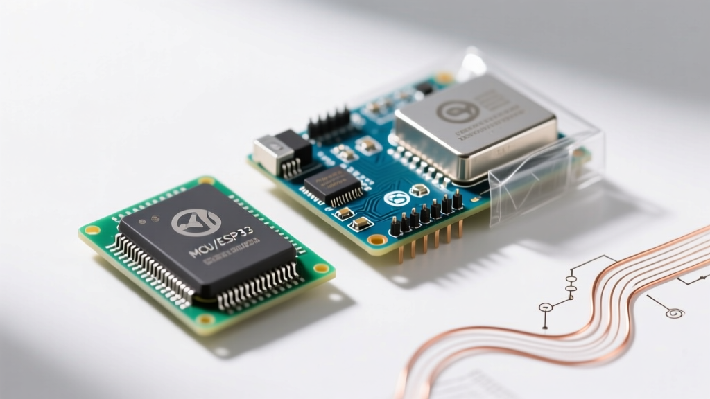
| CMOS IC / MCU | Package blistering, "popcorn" cracks | Dead short on VCC, latch-up, erratic logic | Moisture ingress, ESD, reflow thermal shock |
Passive Component Failures: Beyond the Basics
Electrolytic and Polymer Capacitors
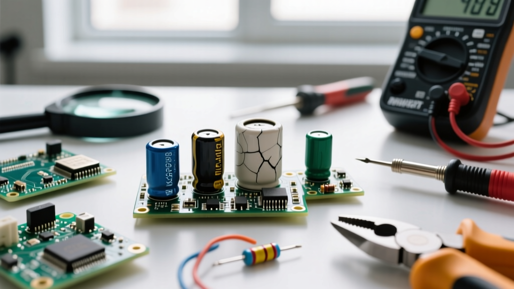
The most ubiquitous of all electronic components defects occurs in aluminum electrolytic capacitors. Over time, the internal electrolyte evaporates through the rubber bung seal. While a standard multimeter might still read the correct DC capacitance, the Equivalent Series Resistance (ESR) skyrockets. For example, a standard 1000µF 16V capacitor should exhibit an ESR below 0.1Ω at 100kHz. If your ESR meter reads >1.5Ω, the component is functionally dead, even if it looks pristine. Always test in-circuit with a dedicated ESR meter to avoid desoldering unnecessary parts.
MLCC Flex Cracking
Multilayer Ceramic Capacitors (MLCCs) suffer from a silent defect: flex cracking. When a PCB bends during depanelization or chassis mounting, the brittle barium titanate dielectric fractures. This is especially prevalent in large case sizes (1210 or 1812) with high capacitance values (>10µF). This creates a high-resistance short that eventually arcs over, causing a catastrophic thermal runaway. Visually, these cracks are microscopic; electrically, they manifest as intermittent leakage currents that spike under thermal load. Using X7R or X5R dielectrics with soft-termination technology (like KEMET's Flexible Termination series) mitigates this specific mechanical defect.
Resistors: Carbon vs. Metal Film
Carbon composition resistors are notorious for absorbing moisture, which causes their resistance to drift upwards over decades. Conversely, modern metal film resistors (e.g., Vishay MRS25 series) rarely drift; they fail open. A common defect signature is a micro-fracture in the resistive film caused by pulse overloads. If a 1/4W metal film resistor is subjected to a 50W transient spike, the helical cut in the film acts as a fuse, vaporizing the connection while leaving the outer epoxy coating completely intact. A reading of infinite ohms (OL) on a visually perfect resistor is a guaranteed open-circuit defect.
Active Component and IC Defect Signatures
MOSFETs and Power Transistors
Power MOSFETs, such as the widely used IRF3205, typically fail in a dead-short state between Drain and Source. This is usually triggered by Avalanche breakdown (exceeding the Vds rating) or Gate punch-through (exceeding the ±20V Vgs limit). Over time, gate oxide degradation can also cause threshold voltage (Vth) drift, leading to inefficient switching and excess heat. To test a MOSFET for a short-circuit defect using a digital multimeter in diode mode:
- Short all three pins (Gate, Drain, Source) together to discharge internal capacitance.
- Place the red probe on the Source and black on the Drain. You should read the body diode drop (typically 0.4V to 0.6V).
- Reverse the probes (Red on Drain, Black on Source). It should read OL (Open Loop).
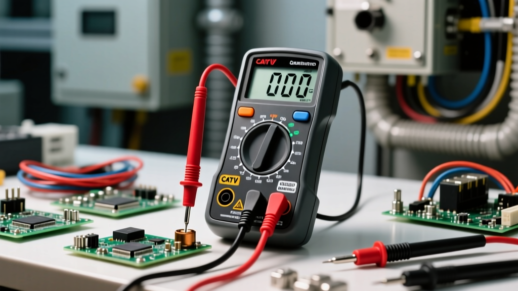
- If it reads near 0.00V in both directions, the MOSFET has suffered a catastrophic short-circuit defect and must be replaced.
Microcontrollers and the "Popcorn" Effect
Moisture Sensitivity Level (MSL) defects plague surface-mount ICs. If an MCU like the STM32F4 series is exposed to ambient humidity and then subjected to 260°C reflow temperatures, the trapped moisture vaporizes instantly. This creates internal delamination and the famous "popcorn" effect, where the IC package physically cracks. According to the IPC-A-610 standard for electronic assemblies, any visible cracking or blistering on an IC encapsulation is an immediate reject criterion. Always bake MSL-sensitive components in a convection oven at 125°C for 24 hours before hand-soldering or reworking to drive out absorbed moisture.
Expert Insight: According to failure analysis data from the NASA Electronic Parts and Packaging (NEPP) Program, a significant majority of field failures in harsh environments are not caused by the silicon die itself, but by packaging defects, wire bond fatigue, and solder joint degradation. Always inspect the interconnects and thermal vias before condemning the IC silicon.
Step-by-Step Defect Isolation Workflow
When troubleshooting a faulty PCB, avoid randomly replacing parts. Follow this non-destructive testing (NDT) sequence to isolate electronic components defects efficiently:
- Step 1: Thermal Profiling. Power the board and use a thermal camera to scan for abnormal hotspots. A defective shorted ceramic capacitor or a latched-up CMOS IC will glow brightly on the thermal display against the cooler PCB substrate.
- Step 2: Voltage Injection. If a short is detected on a power rail, inject a low voltage (e.g., 1V at 2A) into the shorted rail using a bench power supply. The defective component will dissipate the heat, making it instantly visible to your thermal camera or even a drop of isopropyl alcohol (which will boil off the hot part).
- Step 3: Impedance Mapping. Use an oscilloscope with a near-field magnetic probe to trace high-frequency noise back to its source. Defective decoupling capacitors will show massive ringing on the VCC rails that a standard multimeter cannot detect.
Essential Diagnostic Tools for 2026
- ESR Meter: DER EE DE-5000 or Smart Tweezers ST5S ($130 - $400). Essential for identifying dried-out electrolytic capacitors without desoldering.
- Thermal Camera: InfiRay P2 Pro or FLIR C5 ($450 - $700). Crucial for spotting shorted MLCCs and latched-up ICs via heat signatures.
- Oscilloscope: Siglent SDS1000X HD series ($500 - $800). 12-bit ADC resolution allows you to spot micro-defects in power supply ripple that older 8-bit scopes miss.
- Curve Tracer: Octavius DR-1 or similar semiconductor analyzers ($200+). Allows you to map the V-I characteristics of unknown or suspect transistors against known good datasheets.
Frequently Asked Questions
Can a multimeter detect all electronic components defects?
No. A standard multimeter only measures DC resistance and basic capacitance. It cannot detect Equivalent Series Resistance (ESR) in capacitors, which is the most common failure mode, nor can it test the high-frequency switching characteristics of a degraded MOSFET or the leakage current of a stressed MLCC.
What causes "tombstoning" in SMD components?
Tombstoning is a soldering defect, not an internal component defect. It occurs when surface tension on one pad of an SMD resistor or capacitor pulls the part upright during reflow. This is usually caused by uneven pad heating, incorrect stencil aperture design, or oxidized component terminations preventing proper solder wetting.
How do I prevent ESD defects when handling ICs?
Electrostatic Discharge (ESD) can punch through the thin gate oxides of modern nanometer-scale ICs. Always use a grounded wrist strap, work on a dissipative mat, and utilize ionizers in low-humidity environments to neutralize static charges before handling sensitive logic gates or microcontrollers.