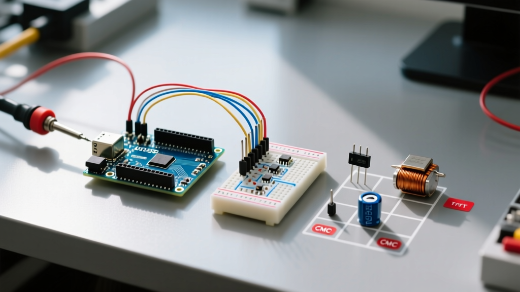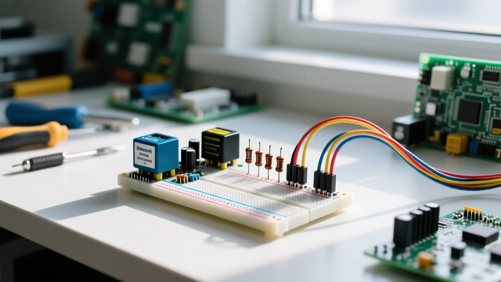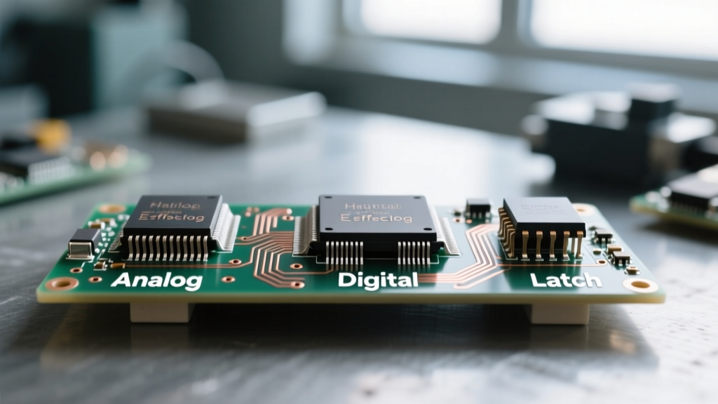

The Core Distinction in PCB Diagnostics
When a printed circuit board (PCB) fails, the urge to immediately start desoldering parts is strong. However, effective troubleshooting requires a systematic understanding of how active and passive electronic components degrade over time. Passive components (resistors, capacitors, inductors) do not introduce power gain or control current flow via a secondary signal; they simply store energy, dissipate heat, or filter frequencies. Active components (transistors, diodes, integrated circuits) rely on semiconductor junctions to amplify signals, switch power, and regulate logic.
In modern 2026 electronics, where high-density surface-mount technology (SMT) and lead-free soldering are standard, failure modes have shifted. Thermal cycling and electromigration now cause microscopic faults long before catastrophic smoke-and-fire failures occur. This guide provides a deep-dive methodology for isolating faults across both component categories using professional-grade diagnostic techniques.
The 2026 Diagnostic Workbench: Beyond the Basic Multimeter
You cannot accurately troubleshoot active and passive electronic components with a cheap $15 multimeter. Precision diagnostics require tools that can measure parasitic properties and dynamic thermal states.
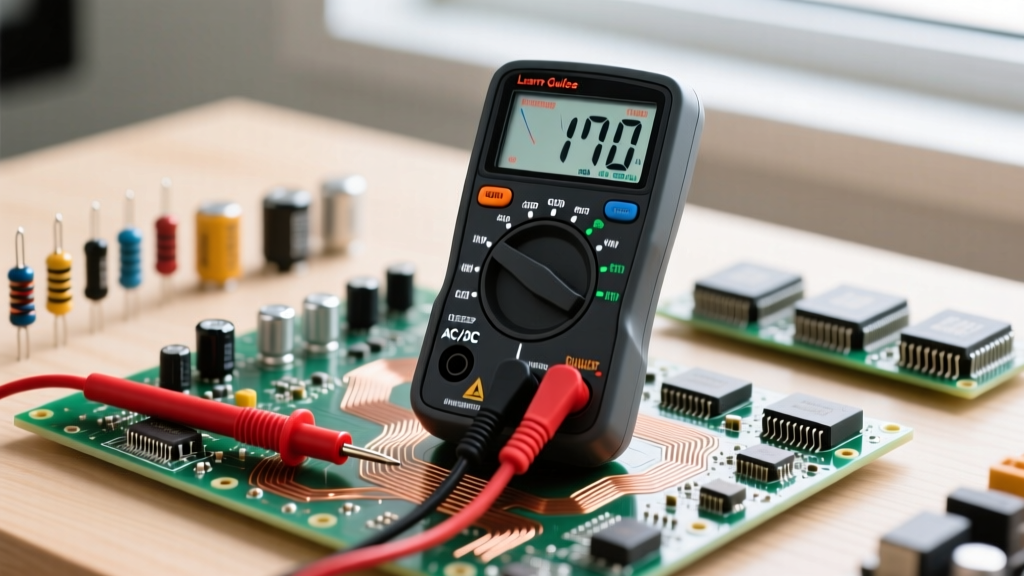
- True-RMS Multimeter: The Fluke 117 ($180-$200) or Fluke 87V ($450) is mandatory for accurate AC/DC readings in noisy environments. Basic meters fail to read the RMS voltage of non-linear switching power supplies accurately.
- ESR Meter: The Atlas ESR70 ($115) is essential for in-circuit capacitor testing. It applies a 100kHz AC signal to measure Equivalent Series Resistance without triggering the semiconductor junctions of surrounding active components.
- Thermal Imaging Camera: The FLIR C5 ($549) or InfiRay P2 Pro ($250) allows you to spot localized hotspots caused by increased Rds(on) in MOSFETs or high ESR in capacitors before the board even powers off.
- Oscilloscope: A 4-channel scope like the Siglent SDS1204X-E ($400) is required to visualize ground bounce, ringing, and gate-drive plateaus in active switching circuits.
Troubleshooting Passive Components: The Silent Failures
Passive components rarely fail catastrophically; instead, they drift out of tolerance, leading to erratic circuit behavior that is notoriously difficult to trace.
1. Capacitors: ESR and Dielectric Absorption
Electrolytic capacitors are the most common point of failure in power supplies. As the liquid electrolyte evaporates over years of thermal stress, the capacitance might only drop slightly, but the Equivalent Series Resistance (ESR) skyrockets. A 100µF 16V electrolytic capacitor should have an ESR below 0.5Ω. If your ESR meter reads 3Ω or higher, the capacitor is effectively an open circuit at high switching frequencies, causing massive output voltage ripple.
MLCC (Multi-Layer Ceramic Capacitor) Edge Cases: In high-fidelity audio or precision analog circuits, Class 2 MLCCs (like X7R or Y5V) exhibit the piezoelectric effect. They can act as microphones, converting mechanical vibration into electrical noise (microphonics). If you are troubleshooting unexplained noise in an audio preamp, physically tapping the MLCCs with a non-conductive probe while monitoring the output on an oscilloscope will confirm this failure mode.
Safety Warning: Always discharge high-voltage DC bus capacitors using a high-wattage bleed resistor (e.g., 10kΩ 5W) before probing. A dead short with a screwdriver can vaporize PCB traces, destroy the capacitor's internal structure, and cause severe injury.2. Resistors: Thermal Drift and Shunt Degradation
Standard carbon-film resistors rarely fail unless subjected to massive over-current, which manifests as visible charring. However, in precision current-sensing applications, shunt resistors suffer from thermal drift. A 10mΩ current sense resistor with a 100ppm/°C temperature coefficient will change its resistance by 1% for every 100°C rise. If a motor controller is tripping its over-current protection prematurely, measure the shunt resistance using a 4-wire Kelvin measurement to eliminate test-lead resistance from the equation.
3. Inductors: Core Saturation and Micro-Shorts
Inductors fail primarily through insulation breakdown between the copper windings. This creates internal micro-shorts that reduce the overall inductance and increase DC resistance (DCR). Furthermore, if an inductor is undersized for the peak current, the magnetic core will saturate. When saturation occurs, the inductor momentarily acts like a straight piece of wire, causing massive current spikes that usually destroy the active switching MOSFET driving it.
Troubleshooting Active Components: The Power Handlers
Active components rely on delicate semiconductor junctions. Troubleshooting them requires understanding both their static DC properties and their dynamic switching characteristics. For foundational testing techniques using standard meters, refer to this comprehensive multimeter guide by SparkFun.
1. Diodes and Rectifiers: Forward Voltage and Reverse Leakage
A standard silicon diode should exhibit a forward voltage drop (Vf) of 0.5V to 0.7V, while a Schottky diode will read 0.15V to 0.3V. If your multimeter's diode test mode reads 'OL' (Open Loop) in both directions, the junction is blown. If it reads near 0.00V in both directions, it is shorted. The hidden failure mode is reverse leakage. A diode might pass a standard multimeter test but leak milliamps of current when subjected to the full reverse-bias voltage of the circuit, causing severe thermal runaway under load.
2. MOSFETs: Rds(on) Degradation and Gate Threshold Shifts
Metal-Oxide-Semiconductor Field-Effect Transistors (MOSFETs) are the workhorses of modern power electronics. When a MOSFET fails, it usually fails shorted (Drain-to-Source). However, a more insidious failure is the degradation of the Rds(on) (Drain-Source On-Resistance). For example, a logic-level IRLZ44N should have an Rds(on) of roughly 15mΩ at room temperature. If thermal cycling has damaged the silicon lattice or the die-attach solder, the Rds(on) might climb to 100mΩ. This causes the MOSFET to dissipate six times more heat (P = I²R), leading to eventual thermal destruction.
To test a MOSFET in-circuit, you must ensure the gate is discharged. Use a 10kΩ resistor to bridge the Gate and Source pins, then measure the resistance between Drain and Source. For advanced dynamic troubleshooting, use an oscilloscope to probe the Gate pin during operation. If the 'Miller Plateau' (the flat region of the gate charging curve) is excessively long or ringing violently, the gate driver IC may be failing, or the MOSFET's internal gate capacitance (Ciss) has degraded.
3. Integrated Circuits (ICs): Decoupling and Ground Bounce
Microcontrollers and logic ICs rarely fail internally unless subjected to electrostatic discharge (ESD) or overvoltage. When an IC behaves erratically, the fault usually lies in its decoupling network. Every VCC pin requires a 100nF MLCC capacitor placed as physically close to the pin as possible. If this passive component fails (cracks due to board flexion), the IC will experience 'ground bounce'—a momentary spike in the local ground reference during high-speed logic switching, causing the CPU to reset or drop communication packets.
Failure Mode Matrix: Active vs. Passive
Understanding the typical failure states of active and passive electronic components speeds up the diagnostic process immensely. Consult the matrix below when formulating your testing strategy.
| Component Type | Primary Failure Mode | Diagnostic Tool | Typical In-Circuit Reading (Faulty) |
|---|---|---|---|
| Electrolytic Capacitor | High ESR / Dried Electrolyte | ESR Meter (100kHz) | > 2.0Ω (for 100µF+ caps) |
| MLCC Capacitor | Short Circuit / Flex Cracking | Multimeter (Resistance) | < 10Ω across power rails |
| Power MOSFET | Drain-Source Short / Gate Punch-through | Multimeter (Diode Mode) | 0.00V drop between D and S |
| Schottky Diode | Thermal Runaway / Reverse Leakage | Thermal Camera / Curve Tracer | Localized hotspot (>80°C at low load) |
| Current Shunt Resistor | Thermal Drift / Solder Joint Fatigue | 4-Wire Kelvin Ohmmeter | > 5% deviation from schematic value |
Step-by-Step Isolation Protocol
When faced with a dead or malfunctioning board, follow this strict isolation protocol to prevent chasing ghosts and damaging functional components.
- Visual and Olfactory Inspection: Use a 10x loupe to inspect for cracked MLCCs, bulging electrolytic capacitors, and scorched FR4 fiberglass. Smell the board; vaporized flux and burnt silicon have distinct, unmistakable odors.
- Power Rail Short Testing: Before applying power, use a multimeter to check the resistance between VCC and GND. A reading below 5Ω on a digital logic board indicates a shorted decoupling capacitor or a failed power management IC (PMIC).
- Thermal Profiling: If no dead short is present, power the board using a current-limited bench supply (set to 5V, 0.5A). Use a thermal camera to identify components drawing abnormal quiescent current. A faulty ceramic capacitor or a shorted MOSFET will light up on the thermal display within seconds.
- Signal Injection and Tracing: For analog or RF circuits, inject a known signal at the input and trace it through the active stages using an oscilloscope. The stage where the signal disappears or heavily distorts contains the faulty active or passive component.
- Component Extraction: Once isolated, desolder the suspect component. Never trust an in-circuit measurement for absolute confirmation. Parallel circuit paths can make a perfectly good component read as faulty. Measure the extracted part in isolation using precision tools.
Conclusion
Troubleshooting active and passive electronic components is an exercise in applied physics. By moving beyond simple continuity checks and embracing advanced diagnostics like ESR profiling, thermal imaging, and dynamic oscilloscope analysis, you can identify the root cause of PCB failures with surgical precision. For further reading on capacitor behavior and dielectric losses, the technical resources provided by Fluke's electrical testing guides and Electronics Tutorials offer excellent supplementary data for your bench reference library.