
The Core Principle: How a Potentiometer Works as a Voltage Divider
A potentiometer is a three-terminal electromechanical component consisting of a fixed resistive track and a sliding contact (the wiper). When you ask how does a potentiometer work, the most precise answer is that it functions as an adjustable voltage divider. By applying a reference voltage across the two outer terminals (pins 1 and 3), the wiper (pin 2) taps into a specific point along the resistive material—carbon composition, cermet, or wirewound—to output a proportional voltage.
The governing equation is straightforward: V_out = V_in × (R_2 / (R_1 + R_2)), where R_1 is the resistance between pin 1 and the wiper, and R_2 is the resistance between the wiper and pin 3. In a 10kΩ linear potentiometer connected to a 5V supply, rotating the shaft to the exact mechanical center yields 2.5V at the wiper. This principle is foundational for volume controls, joystick position sensing, and feeding analog reference voltages into an ESP32 or Arduino ADC.
Multimeter Setup and Safety Categories for Potentiometer Testing
Before probing the terminals, you must configure your meter correctly and assess the voltage environment. Measuring resistance on a live circuit will blow your multimeter's internal fuse and yield meaningless data.
Multimeter Configuration for Bench Testing
- Dial Position: Resistance (Ω) for testing the physical track; DC Volts (V⎓) for verifying the voltage divider output in a live low-voltage circuit.
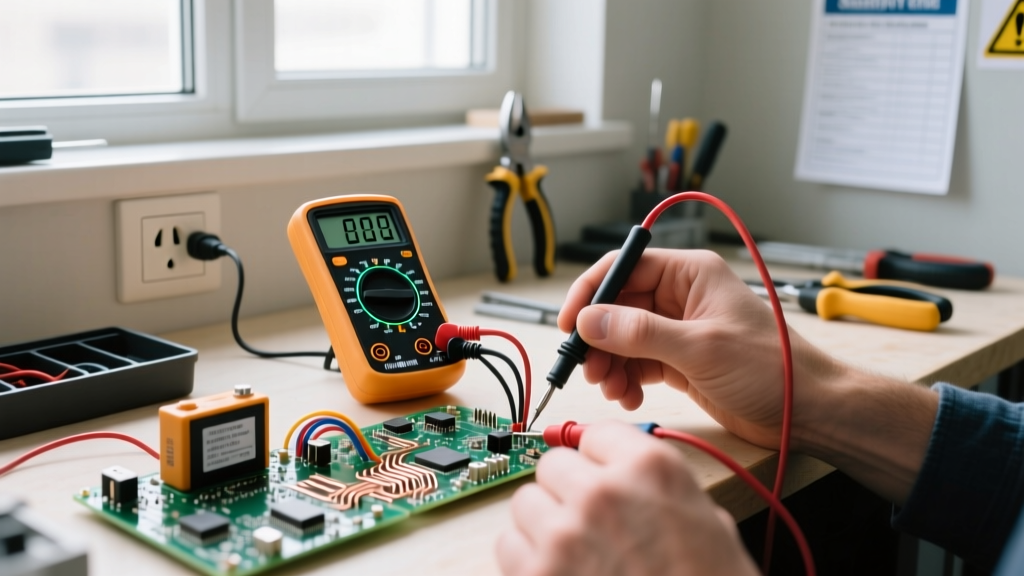
- Lead Jacks: Black lead in COM, Red lead in the V/Ω/mA jack.
- Range Setting: Auto-ranging is preferred. If using a manual meter, select the 20kΩ range for a standard 10kΩ pot, or the 200kΩ range for a 100kΩ pot.
- Zeroing: Touch the probes together. The display should read < 0.5Ω. If it reads higher, subtract this lead resistance from your final measurements.
Step-by-Step Probe Placement and Expected Readings
To accurately determine if a potentiometer is functional, it must be isolated from the circuit. Parallel paths through other components (like pull-down resistors or op-amp feedback loops) will skew your readings. Desolder the component or lift at least one outer leg from the PCB.
Test 1: Total Track Resistance (Pins 1 and 3)
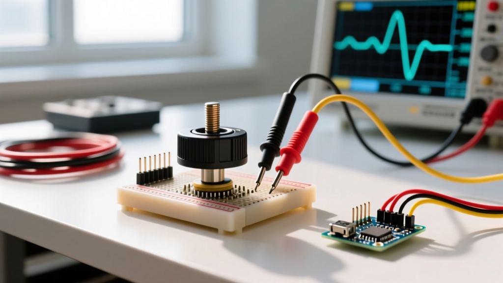
Place your red probe on pin 1 and your black probe on pin 3 (polarity does not matter for resistance). Rotate the shaft fully back and forth. The reading should remain completely static. For a 10kΩ carbon track pot, expect a reading between 8kΩ and 12kΩ, as carbon composition tracks typically carry a 20% manufacturing tolerance. Cermet trimpots (like the Bourns 3296 series) will hold a tighter 10% tolerance.
Test 2: Wiper Tracking and Linearity (Pins 1-2 and 2-3)
Keep one probe on an outer pin (e.g., pin 1) and move the other probe to the center wiper (pin 2). Slowly rotate the shaft from one extreme to the other. The resistance should sweep smoothly from near 0Ω up to the total track resistance. Repeat this between pin 2 and pin 3; the sweep should occur in the opposite direction.
| Probe Placement | Shaft Position | Good Reading (Expected) | Bad Reading (Fault Indicator) |
|---|---|---|---|
| Pin 1 to Pin 3 | Any position | 10kΩ (±20%) static | OL (Open) or fluctuating values |
| Pin 1 to Pin 2 (Wiper) | Fully CCW | ~0Ω to 50Ω | > 100Ω (dirty wiper contact) |
| Pin 1 to Pin 2 (Wiper) | Center (50%) | ~5kΩ | Erratic jumping (e.g., 4k to 7k) |
| Pin 1 to Pin 2 (Wiper) | Fully CW | ~10kΩ | OL (wiper lost contact with track) |
Note: The sum of the resistance measured from Pin 1-to-2 and Pin 2-to-3 at any given shaft position must exactly equal the Pin 1-to-3 total resistance.
Common Mistakes That Yield Misleading Resistance Values
When diagnosing potentiometer circuits, bench technicians frequently encounter phantom faults caused by measurement errors rather than component failure.
- Measuring In-Circuit: If you measure a 10kΩ pot while it is still soldered to a board that features a 10kΩ pull-down resistor on the wiper, your meter will read the parallel equivalent (5kΩ). Always isolate the component.
- Ignoring Wiper Noise (Jitter): A multimeter's slow refresh rate might show a steady 5.00kΩ, but an oscilloscope or microcontroller ADC will reveal micro-second dropouts caused by carbon dust or oxidation on the track. If an audio amp crackles when you turn the knob, the pot is failing even if the DMM reads the correct static resistance.
- Finger Shunting: When holding a small trimpot in your hand while probing, your skin's resistance (typically 50kΩ to 200kΩ depending on moisture) can parallel the track, slightly skewing readings on high-value (100kΩ+) potentiometers. Clamp the component in a vise or use alligator clip leads.
- Confusing Tapers: If you rotate the shaft to the mechanical center and read 1.5kΩ on a 10kΩ pot, it isn't necessarily broken. It may be an Audio (Logarithmic) taper pot, designed to match human hearing perception, which intentionally skews resistance to one side of the physical travel.
Diagnostic Decision Tree: Repair, Clean, or Replace?
Use the following decision matrix to determine your next step based on your multimeter readings and physical inspection. Do not attempt to repair a sealed carbon track; replacement is the only reliable fix for internal track damage.
| Symptom / Measurement | Root Cause Diagnosis | Required Action & Concrete Part Pick |
|---|---|---|
| Pins 1-3 read OL (Open Loop) | Resistive track fractured or internal copper lead snapped off the wafer. | Replace. Discard unit. Install Bourns PTV09A-4025F-B103 (10kΩ linear, 25mm knurled shaft, PCB mount). |
| Total resistance (1-3) is correct, but wiper (1-2) exhibits random resistance jumps or dropouts during rotation. | Oxidation, carbon dust, or dried lubricant on the wiper contact fingers. | Clean. Spray DeoxIT D5 (contact cleaner) into the casing slot, rotate 50 times to scrub the track, and re-test. |
| Wiper reads >100Ω at the extreme CCW or CW physical stops. | Wiper contact fingers are bent, worn down, or the end-track silver coating is degraded. | Replace. The mechanical wear cannot be reversed. Swap with the Bourns PTV09A-4025F-B103. |
| Shaft rotates with zero mechanical resistance (spins freely) and output is static. | Internal D-shaft or split-ring clutch has stripped; wiper is no longer coupled to the user-facing shaft. | Replace. Mechanical failure requires a new unit. Swap with the Bourns PTV09A-4025F-B103. |
| Readings are perfectly stable and sweep linearly, but circuit still misbehaves. | Potentiometer is healthy. Fault lies in downstream buffering, ADC reference, or wrong taper selection (Log vs Linear). | Verify Taper/Circuit. Check schematic for required taper. If audio, replace with an Alpha RD901F-40-15K1-B10K (Audio taper). |
By systematically isolating the component, applying the correct meter range, and interpreting the wiper sweep against the total track resistance, you can definitively answer whether a potentiometer is functioning as designed or requires replacement. When in doubt, the Bourns PTV09A series provides a reliable, low-noise cermet/carbon hybrid track that withstands standard bench and field soldering temperatures without degrading the resistive element.