
Decoding IC Electronic Components: The 2026 Reference Guide
Integrated circuits (ICs) are the foundational building blocks of modern electronics, packing thousands to billions of transistors into a single semiconductor die. Whether you are designing a custom PCB, repairing industrial control boards, or prototyping with microcontrollers, understanding how to identify, source, and test IC electronic components is non-negotiable. This comprehensive cheat sheet serves as your bench-side reference for package footprints, part number nomenclature, pinout identification, and advanced diagnostic techniques.
1. IC Package Footprint Matrix
Selecting the right package involves balancing PCB real estate, thermal dissipation, and soldering feasibility. While automated pick-and-place machines handle microscopic pitches with ease, DIYers and repair technicians must consider manual rework capabilities. Below is the definitive 2026 package reference matrix.
| Package Type | Standard Pitch | Typical Pin Count | Manual Solderability | Primary Use Case |
|---|---|---|---|---|
| DIP (Dual In-Line) | 2.54mm (0.1") | 8 to 40 | Excellent (Beginner) | Breadboarding, legacy repair, educational kits |
| SOIC (Small Outline) | 1.27mm (0.05") | 8 to 32 | Good (Intermediate) | General surface-mount logic, op-amps, voltage regulators |
| TSSOP (Thin Shrink) | 0.65mm (0.025") | 14 to 56 | Fair (Advanced) | Microcontrollers, memory, dense logic arrays |
| QFP (Quad Flat Pack) | 0.50mm to 0.80mm | 32 to 256+ | Difficult (Expert) | High-pin-count microcontrollers, FPGAs, DSPs |
| QFN (Quad Flat No-lead) | 0.40mm to 0.65mm | 16 to 72 | Poor (Hot Air/Reflow) | RF modules, power management, space-constrained IoT |
| BGA (Ball Grid Array) | 0.40mm to 1.27mm | 100 to 2000+ | Specialized (Rework Station) | High-end processors, SoCs, advanced computing |
2. Logic Families & Linear IC Nomenclature
A common stumbling block for beginners is deciphering the alphanumeric soup printed on IC electronic components. Manufacturers use structured naming conventions to indicate the silicon family, temperature range, and physical package.
The 74xx vs. 40xx Series
The 74xx series represents standard TTL (Transistor-Transistor Logic) and its CMOS derivatives, operating primarily at 5V (or down to 2V for modern low-voltage variants). The 40xx series is the original CMOS logic family, prized for its wide operating voltage range (3V to 15V) and ultra-low static power consumption.
- 74HC595: High-speed CMOS 8-bit shift register. Widely used for I/O expansion. Typical 2026 pricing: $0.15 - $0.30 in SOIC-16. (Reference the NXP 74HC/HCT595 Datasheet for exact timing diagrams).
- 4017B: CMOS decade counter/divider. Ideal for LED chasers and sequential timing. Typical pricing: $0.25.
Decoding the Prefix and Suffix
Take the part number SN74HC595N as an example:
- SN: Manufacturer prefix (Texas Instruments).
- 74: Commercial temperature range (0°C to 70°C). If this were 54, it would indicate military grade (-55°C to 125°C).
- HC: High-speed CMOS logic sub-family.
- 595: The specific base function (shift register with output latches).
- N: Package designator (N = Plastic DIP).
3. Pin 1 Identification: Visual & Multimeter Methods
Misaligning an IC by a single pin during installation will instantly destroy the silicon due to reverse voltage polarity or ground-to-VCC shorting. Always verify Pin 1 using multiple methods before applying power.
Visual Markings
- The Index Notch: A semi-circular cutout at one end of the IC body. Pin 1 is always to the immediate left of the notch when the text is read left-to-right.
- The Beveled Edge: Many SOIC and TSSOP packages feature a chamfered or beveled edge along the side where Pin 1 resides.
- The Laser Dot: A small engraved or painted circle near Pin 1. On QFP and BGA packages, this dot is often located in the corner of the substrate.
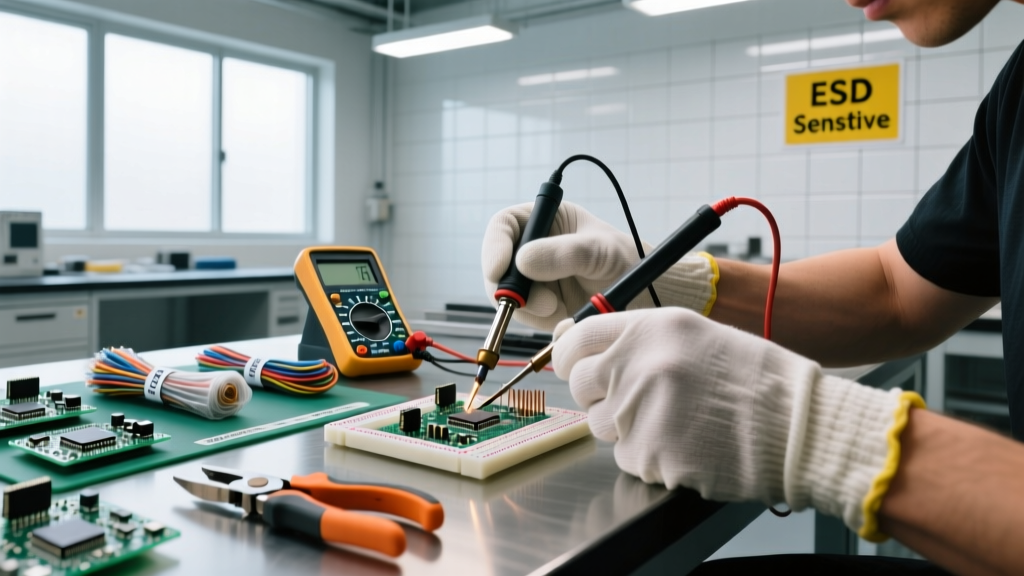
Multimeter Verification (The Continuity Check)
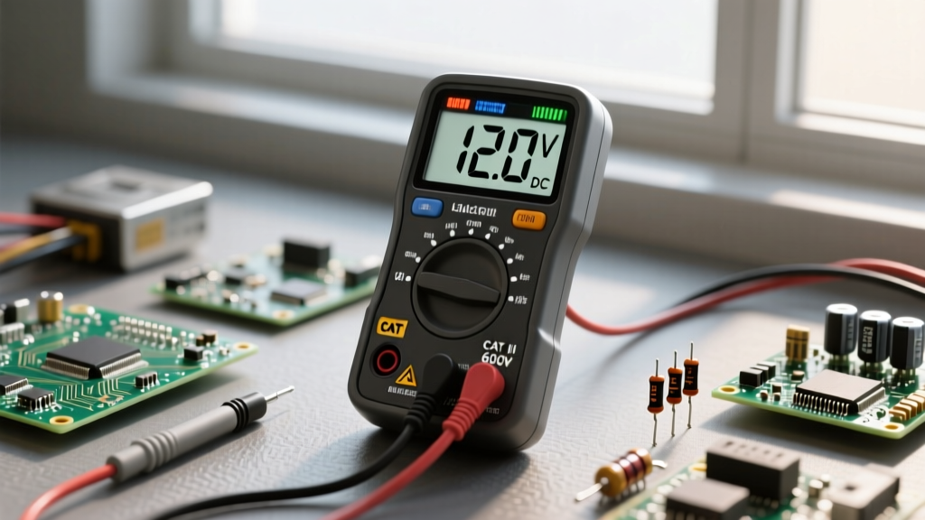
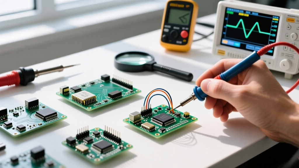
Visual marks can be obscured by conformal coating or flux residue. Use your multimeter in continuity mode. Cross-reference the physical pin with the Microchip ATmega328P Datasheet (or relevant schematic) to find a known ground plane connection. Probe the suspected Pin 1 and a known ground pad; if the schematic shows Pin 1 as VCC, you will get an open loop (OL). If it shows Pin 1 as GND, you will hear a beep.
4. Real-World Failure Modes & Diagnostic Techniques
IC electronic components fail in predictable ways. Understanding these failure modes allows you to diagnose faults without blindly swapping parts.
CMOS Latch-Up
Latch-up occurs when a parasitic thyristor structure inside a CMOS IC is triggered, usually by an input voltage exceeding VCC or a fast voltage transient. This creates a low-impedance path between VCC and GND, drawing massive current. Diagnostic: If an IC becomes instantly hot to the touch upon power-up, but measures normal resistance when unpowered, it has likely suffered latch-up or internal thermal destruction. The only fix is physical replacement.
ESD Gate Oxide Puncture
Electrostatic Discharge (ESD) can puncture the microscopic silicon dioxide gate insulation inside MOSFETs and CMOS logic. According to the ESD Association Standards, human body model (HBM) discharges as low as 100V can damage sensitive nodes. Diagnostic: ESD damage often manifests as "leaky" pins. Use your multimeter's diode test mode. Place the red probe on the IC's GND pin and the black probe on the suspected I/O pin. A healthy protection diode will read between 0.4V and 0.7V. A reading of 0.0V indicates a shorted (punctured) junction.
Thermal Runaway in Linear Regulators
Linear ICs like the LM317 or LM7805 dissipate excess voltage as heat. If the thermal paste dries out or the heatsink is undersized, the junction temperature exceeds the 150°C thermal shutdown threshold. Repeated thermal cycling eventually cracks the internal bond wires. Pro-Tip: Use a high-resolution thermal camera like the InfiRay P2 Pro to identify linear ICs running above 85°C in ambient room conditions, indicating an impending thermal failure.
5. Power Sequencing in Complex Microcontrollers
When working with advanced IC electronic components like multi-core SoCs or FPGAs, power sequencing is critical. Unlike a simple 5V logic chip, modern processors require multiple voltage rails (e.g., 1.1V for the core, 1.8V for PLLs, and 3.3V for I/O) to be powered up and down in a strict chronological order.
Expert Warning: Applying 3.3V to the I/O pins before the 1.1V core rail is active can forward-bias internal parasitic diodes, back-feeding power into the unpowered core. This "phantom powering" can corrupt internal flash memory or permanently damage the silicon. Always use dedicated PMICs (Power Management ICs) like the TI TPS65217 to enforce hardware-level sequencing.
6. Sourcing Authentic ICs in the Modern Supply Chain
The secondary market is flooded with counterfeit ICs. Fraudsters use "blacktopping" (sanding off original text and printing fake part numbers) or pulling used chips from e-waste and re-tinning the leads. A fake ATmega328P might actually be a re-marked, lower-spec ATmega168 that crashes when you upload a complex sketch.
The Anti-Counterfeit Checklist
- Use Aggregators: Rely on platforms like Octopart or Findchips to locate stock exclusively from authorized distributors (Mouser, DigiKey, Farnell, Arrow).
- Inspect the Leads: Genuine ICs have uniform, matte-finish leads. Counterfeit pulled chips often show scratch marks on the pins from previous desoldering, or an unnaturally bright, uneven solder dip.
- Check the Date Code: The 4-digit date code (YYWW) on the chip should match the manufacturer's lot traceability. If a vendor claims to have "new" stock of a part that went obsolete in 2019, the date code will expose the lie.
- Decapsulation (Destructive): For high-volume or critical aerospace/medical projects, use fuming nitric acid to dissolve the epoxy package and inspect the silicon die under a microscope to verify the manufacturer's microscopic logo and die-rev markings.
Summary
Mastering IC electronic components requires moving beyond simple part number matching. By understanding package geometries, decoding manufacturer nomenclature, rigorously verifying pinouts, and employing advanced multimeter diagnostics, you transition from a hobbyist to a competent electronics engineer. Keep this cheat sheet at your workbench to ensure every build, repair, and prototype is executed with precision and confidence.