
Pushing Past FR4: The 2026 RF Prototyping Reality
As we move deeper into 2026, the DIY electronics landscape has shifted dramatically. With Wi-Fi 7 (802.11be) operating across the 2.4, 5, and 6 GHz bands, and automotive radar kits becoming accessible to hobbyists, standard FR4 fiberglass is no longer sufficient for high-frequency prototyping. At 5.8 GHz and above, the loss tangent of FR4 essentially turns your PCB traces into resistors, bleeding your RF signal into the substrate as heat. To build functional high-frequency transceivers, Doppler radar modules, or low-noise amplifiers (LNAs), makers must turn to advanced dielectrics.
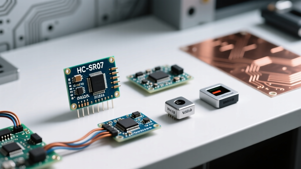
This is where enterprise-grade materials enter the hobbyist workspace. Specifically, navigating the catalog of AGC electronic components business headquarters products reveals a treasure trove of PTFE-based laminates (marketed under the Fluon+ brand), synthetic quartz substrates, and advanced ceramic packages. While AGC Inc. (formerly Asahi Glass) is globally recognized for architectural and automotive glass, their electronics division produces some of the most critical high-frequency materials used in 5G/6G infrastructure and satellite communications. This guide will show you how to source, handle, and build with these elite materials in your home lab.
Decoding the AGC Corporate Catalog for Makers
When hobbyists attempt to browse AGC's official electronics business division, the sheer scale of their B2B offerings can be overwhelming. The "business headquarters products" designation generally refers to their core, proprietary material science lines managed directly from their Tokyo and regional headquarters, rather than commoditized off-the-shelf interconnects. For the DIY RF engineer, three specific product lines are highly relevant:
- Fluon+ High-Frequency Laminates: PTFE (Teflon) and hydrocarbon-based copper-clad laminates designed for ultra-low transmission loss.
- Multilayer Ceramic Substrates: Used as base plates for high-power RF amplifiers requiring extreme thermal conductivity.
- Ceramic Leadless Chip Carriers (LCC): Hermetic and near-hermetic packaging for sensitive RF ICs, minimizing parasitic capacitance at the pin transitions.
Material Matrix: FR4 vs. Rogers vs. AGC Fluon+
Understanding why you would go through the trouble of sourcing AGC materials requires looking at the raw physics of the substrates. Below is a comparison matrix for a standard 0.508mm (20 mil) substrate thickness at 5.8 GHz.
| Material | Dielectric Constant (Dk) | Dissipation Factor (Df) | Thermal Conductivity | Est. Cost (per sq in) |
|---|---|---|---|---|
| Standard FR4 (370HR) | 4.2 to 4.8 (varies) | 0.021 | 0.30 W/mK | $0.05 |
| Rogers RO4350B | 3.48 ± 0.05 | 0.0037 | 0.69 W/mK | $0.40 |
| AGC Fluon+ LM730 (PTFE) | 2.2 ± 0.04 | 0.0009 | 0.25 W/mK | $0.85 |
Note: As highlighted in expert RF resources like Microwaves101's guide on PTFE substrates, the ultra-low Df of PTFE materials like Fluon+ is what preserves signal integrity in millimeter-wave and high-microwave applications.
Step-by-Step Build: 5.8 GHz ISM Doppler Radar Module
Let us apply these materials to a practical project: building a 5.8 GHz continuous-wave (CW) Doppler radar sensor for precision motion tracking. This requires a stable Dk to maintain the exact phase relationship between the transmit (TX) and receive (RX) patch antennas.
Step 1: Substrate Preparation and the PTFE Adhesion Problem
Unlike FR4, pure PTFE is chemically inert. Copper will not naturally adhere to it, and standard through-hole plating processes will fail because the electroless copper bath cannot grip the via walls. If you are ordering raw AGC Fluon+ laminates, you must ensure they are factory-treated, or you must chemically etch the via barrels yourself.
- Sodium Naphthalene Etching: To plate vias in PTFE, the via walls must be defluorinated using a sodium naphthalene complex (often sold as Tetra-Etch). This strips the fluorine atoms from the surface, leaving a carbon-rich layer that copper can bond to.
- Safety Warning: This chemical process is highly reactive and generates toxic byproducts. For DIYers, it is vastly superior to purchase AGC laminates that come with pre-drilled, plasma-treated, and copper-plated vias from the distributor.
Step 2: Microstrip Routing and Impedance Control
For a 50-ohm microstrip line on a 0.508mm AGC Fluon+ substrate (Dk = 2.2), the trace width must be precisely calculated. Using standard RF calculators, a 50-ohm trace on this specific material requires a width of approximately 1.57mm.
Expert Tip: When milling PTFE laminates on a desktop CNC (like a Bantam PCB Miller), use a single-flute up-cut endmill at 15,000 RPM with a very slow feed rate (100 mm/min). PTFE is soft and gummy; standard two-flute bits will tear the copper cladding away from the substrate, ruining your impedance continuity.
Step 3: Via Fencing for Waveguide Isolation
At 5.8 GHz, surface waves can propagate through the substrate and couple your TX signal directly into your RX low-noise amplifier, blinding the radar. To prevent this, you must build a "via fence" around the RF traces. According to IPC-2221 design standards and RF best practices, the spacing between grounding vias must be less than 1/20th of the wavelength in the dielectric. At 5.8 GHz in a Dk 2.2 material, the guided wavelength is roughly 34.8mm. Therefore, your via fence spacing must be tighter than 1.74mm. Place 0.3mm vias every 1.5mm to ensure total isolation.
Sourcing AGC Headquarters Products as a Hobbyist
The most significant hurdle in utilizing AGC electronic components business headquarters products is procurement. AGC primarily operates on a B2B model, supplying massive reels and sheet sizes to tier-one telecom manufacturers. However, DIYers can access these materials through strategic channels:
- Sample Request Programs: AGC Electronics America and their European counterparts frequently honor sample requests for university labs and verified open-source hardware projects. Registering your maker space or LLC and requesting a "Fluon+ Evaluation Kit" can often yield enough 3x3 inch laminates for a dozen prototype boards.
- Specialized RF Surplus: Surplus vendors on platforms like eBay or specialized RF forums frequently liquidate overstock from telecom fabrication houses. Search for "AGC PTFE laminate" or "Fluon+ copper clad" to find pre-cut blanks.
- Distributor Equivalents: While raw laminates are hard to buy in single units, AGC's ceramic packages and high-frequency interconnects are sometimes stocked by specialized distributors like Richardson RFPD or Pasternack, which cater to low-volume RF engineers.
Troubleshooting Edge Cases and Failure Modes
Working with enterprise-grade PTFE and ceramics introduces unique failure modes that do not exist in standard Arduino or FR4 projects.
Delamination During Reflow
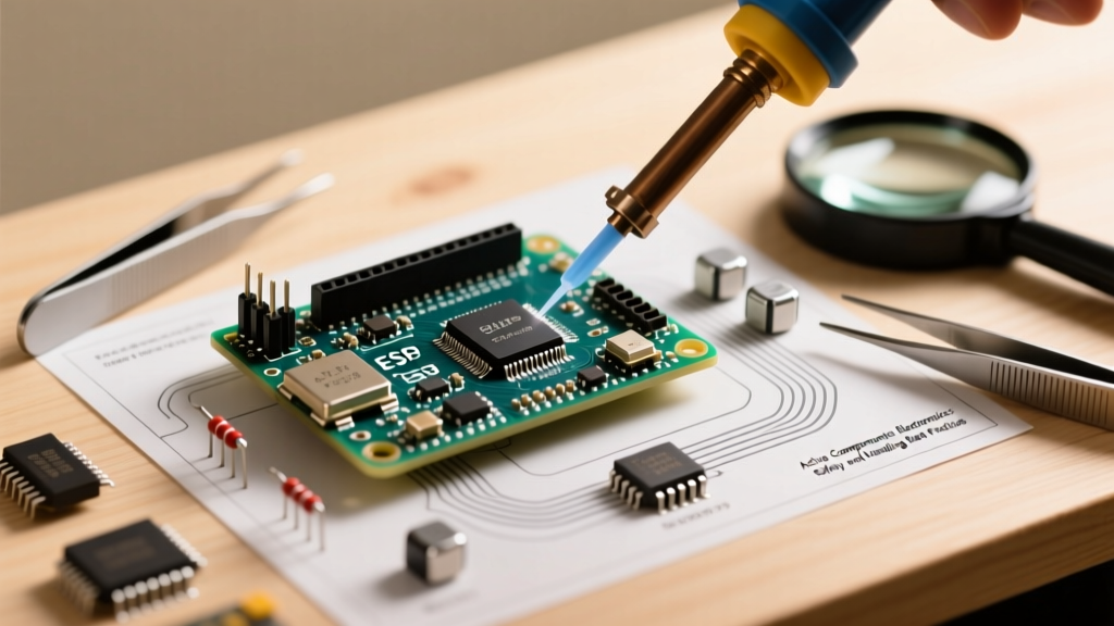
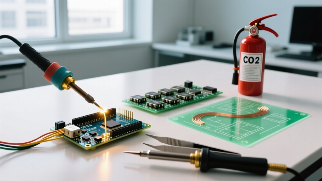
PTFE has a very high melting point (around 327°C), but the bond between the copper cladding and the PTFE substrate can weaken if subjected to prolonged heat. If you are hand-soldering heavy SMA connectors to the board edge, use a localized hot air gun set to 280°C rather than a high-mass soldering iron that might soak the entire edge in heat for minutes. If the copper peels back, your 50-ohm transition is destroyed, resulting in massive return loss (S11).
CTE Mismatch in Ceramic Packages
If you are mounting a bare-die RF MMIC (Monolithic Microwave Integrated Circuit) into an AGC ceramic LCC package, you must account for the Coefficient of Thermal Expansion (CTE). Ceramic expands much less than the silicon die or the gold bonding wires. During the 2026 transition to lead-free, high-temperature solder pastes (which require reflow peaks of 245°C+), the thermal shock can snap gold bond wires. Always use a low-temperature indium-based solder (melting point ~157°C) for die-attach and final package sealing to preserve the structural integrity of the ceramic housing.
Conclusion
Integrating AGC electronic components business headquarters products into your DIY workflow bridges the gap between hobbyist prototyping and commercial aerospace engineering. While sourcing Fluon+ laminates and ceramic packages requires more legwork than ordering standard FR4 from overseas fab houses, the resulting performance at 5.8 GHz and beyond is undeniable. By respecting the unique chemical and thermal properties of PTFE and ceramics, you can build radar, LNA, and Wi-Fi 7 front-ends that rival commercial off-the-shelf modules right from your home workbench.