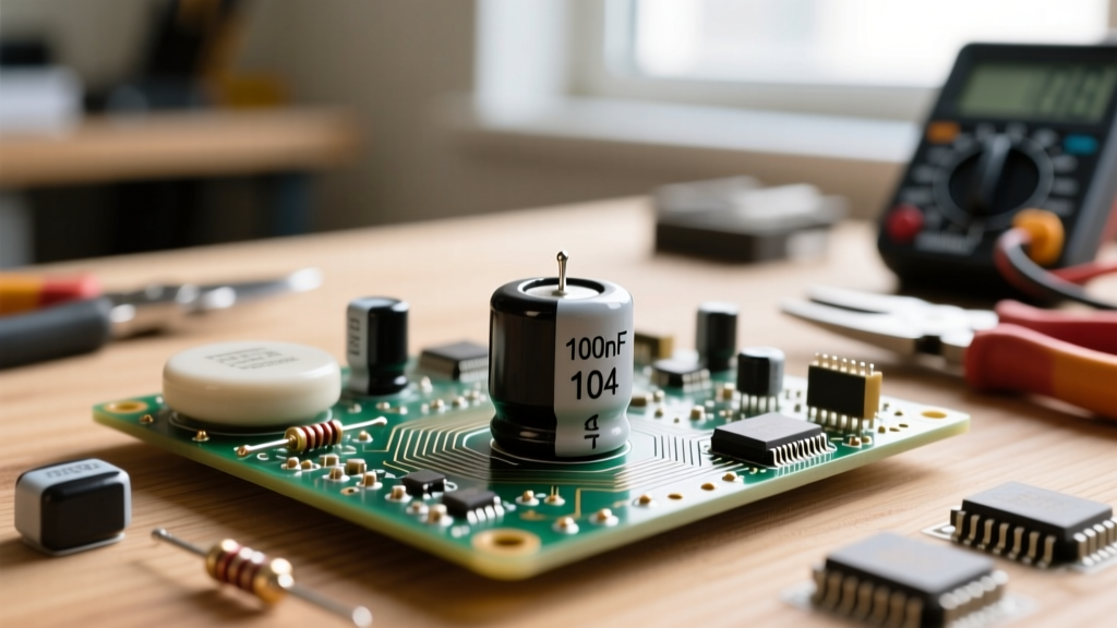
An ampere (amp) is the measure of electrical current, defined practically as one coulomb of electrical charge flowing past a specific point in a circuit every second. While textbooks focus on the physics of electron flow, on the workbench and the jobsite, the ampere is the number that dictates your wire gauge, your breaker size, and exactly how much heat your conductors will generate. In a real installation, amperage is the primary driver of $I^2R$ (current squared times resistance) heating losses. 1 Ampere = 6.242 × 10¹⁸ electrons per second, according to the NIST SI base unit definitions.
People commonly confuse amperes with voltage or watts. Voltage is the electrical pressure pushing the charge, while watts represent the total work being done. Think of voltage as the water pressure in a pipe, and the ampere as the actual gallons per minute flowing through it. If you increase the pressure (volts) without changing the pipe size, you get more flow (amps)—but it is the flow itself that causes friction and heat.
The Math That Matters: A Worked Numeric Example
To understand what an ampere actually changes in a circuit, we need to look at how current interacts with wire resistance. Let us calculate the voltage drop and heat dissipation for a standard 120V AC branch circuit.
- Find the Resistance: According to NEC Chapter 9, Table 8, the DC resistance of uncoated 14 AWG copper is 2.525 ohms per 1,000 feet. Because current must travel to the load and back, your total circuit length is 100 feet (50 ft out + 50 ft return). Total Resistance ($R$) = 2.525 × (100 / 1000) = 0.2525 ohms.
- Calculate Voltage Drop: Using Ohm's Law ($V = I imes R$), the drop is 12A × 0.2525Ω = 3.03 volts. On a 120V nominal system, this is a 2.5% drop, which is well within the NEC's recommended 3% maximum for branch circuits.
- Calculate Heat Dissipation: This is where amperes bite you. Power dissipated as heat in the wire is calculated as $P = I^2R$. So, $12^2 imes 0.2525$ = 144 × 0.2525 = 36.36 watts.
That means 36.36 watts of heat are being generated along that 100-foot run of wire. Because it is spread out, the wire stays cool. But notice the squared relationship: if a fault allowed 24A to flow before the breaker tripped, the heat generated would jump to 145 watts, rapidly degrading the insulation. This squared relationship is why the NFPA National Electrical Code (NEC) strictly ties breaker ampacity to wire gauge.
Where You Meet Amperes in Practice
You will encounter ampere limits across every discipline of electrical and electronics work. Ignoring them is the fastest way to destroy components or start a fire.
- Home Wiring & Panels: Standard NM-B (Romex) cable relies on ampacity tables. 14 AWG is limited to 15A breakers, 12 AWG to 20A, and 10 AWG to 30A. The breaker exists solely to protect the wire from the heat generated by excessive amperes.
- Embedded Systems (Arduino/ESP32): Microcontroller GPIO pins have strict current limits. The Espressif ESP32 datasheet specifies an absolute maximum of 40mA per GPIO pin, with a recommended continuous limit of 20mA. Pulling 50mA to drive a small relay directly will fry the silicon trace inside the chip.
- Battery & Solar Systems: A 100Ah LiFePO4 battery might have plenty of capacity, but its Battery Management System (BMS) dictates the amperage limit. If the BMS MOSFETs are rated for 100A continuous, attempting to pull 120A to run a microwave will cause the BMS to open the circuit to prevent thermal runaway.
- USB-C Power Delivery (PD): Modern USB-C cables are categorized by their ampere rating. A standard cable handles 3A (up to 60W at 20V), while an E-marked cable is required to safely carry 5A (up to 100W or 240W in PD 3.1) without the connector melting.
Scenario Walkthrough: When Ignoring Amps Melts Your Project
Theory is clean; workbenches are messy. Here is a real-world failure scenario that demonstrates what happens when a builder focuses on voltage and ignores amperage.
The Numbers:
Each WS2812B LED pulls roughly 60mA (0.06A) at full white brightness. The strip has 300 LEDs total.
Total Current Draw = 300 × 0.06A = 18 Amps.
The 18 AWG wire used for the main feed is typically rated for about 10A to 14A in chassis wiring, depending on bundling and ambient temperature.
The Outcome:
When the builder commands the strip to turn full white, the LEDs at the far end of the strip glow a dim, sickly yellow instead of bright white. Within three minutes, the 18 AWG zip cord becomes hot to the touch. The PVC insulation softens, and the solder joint at the strip's input pad melts, disconnecting the power and killing the lights.
What Went Wrong:
The builder ensured the power supply was 5V (matching the strip) but completely ignored the 18A draw. Pushing 18A through 18 AWG wire caused two massive issues:
- Severe Voltage Drop: The high current multiplied by the wire's resistance dropped the voltage at the far end of the strip to roughly 3.5V. WS2812B chips need at least 4.5V to render white correctly; below that, the blue and green diodes starve, leaving only red/yellow.
- Thermal Failure: Using $P = I^2R$, the 18A current generated enough localized heat at the high-resistance solder joint and the undersized wire to exceed the melting point of the PVC insulation and the rosin-core solder.
The Fix: For an 18A continuous 5V load, the builder needed to use at least 10 AWG silicone wire for the main feed, or better yet, inject power into the LED strip every 2 meters using 16 AWG wire to keep the amperage in any single run under 5A.
Frequently Asked Questions
What is the difference between an amp and a watt?
Amperes measure the rate of flow of electrical charge, while watts measure the total power (work done) over time. You calculate watts by multiplying volts by amps ($W = V imes A$). A 120V circuit drawing 10A produces 1,200 watts. A 12V circuit drawing 100A also produces 1,200 watts. The wattage is identical, but the 12V circuit requires massively thicker wires to handle the 100A flow without melting.
Why do breakers trip on amps and not volts?
Circuit breakers are designed to protect wires from catching fire, and wire heating is caused by current flow (amps), not electrical pressure (volts). Inside a standard thermal-magnetic breaker, a bimetallic strip bends when heated by the $I^2R$ effect of excessive amperage, tripping the switch. The voltage rating on a breaker (e.g., 120/240V) simply dictates its ability to safely extinguish the electrical arc that forms when the contacts separate, not when it trips.
Can I use a higher amp breaker on the same wire to stop it from tripping?
Absolutely not. This is a severe fire hazard and a direct violation of electrical codes. If a 15A breaker keeps tripping on a 14 AWG wire circuit, it means the connected loads are drawing more than 15A. Swapping to a 20A breaker allows the wire to carry current beyond its safe ampacity, turning the copper conductor inside your walls into a heating element that will eventually ignite the surrounding framing or insulation. The correct fix is to redistribute the loads to a different circuit or run a new, properly sized circuit.