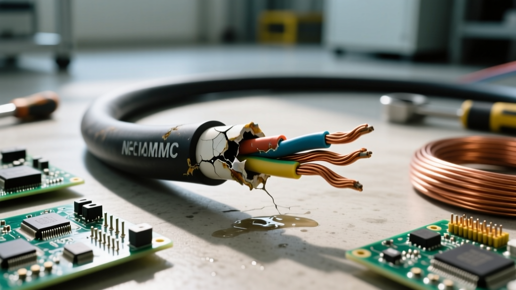

The Anatomy of an NMC Cable Failure
Non-Metallic Clad (NMC) cable is a specialized wiring solution designed for environments where standard NM-B (Romex) would quickly degrade. While NM-B is restricted to dry, indoor locations, NMC cable features a corrosion-resistant, non-metallic outer PVC jacket that allows it to be installed in damp locations, masonry block walls, and areas exposed to mild corrosive elements. However, when NMC cable fails, the root cause is rarely the copper conductors themselves; it is almost always a breakdown of the outer jacket or the internal THHN/THWN insulation due to environmental misuse, thermal overload, or chemical attack.
Troubleshooting NMC cable requires a distinct methodology. Because it is often routed through masonry, tuck-pointed walls, or damp crawlspaces, visual inspection is frequently obstructed. Electricians must rely on a combination of insulation resistance testing, thermal imaging, and an intimate understanding of National Electrical Code (NEC) Article 334 to accurately diagnose faults. Below, we break down the exact failure modes of NMC cable and the field-tested protocols required to isolate and repair them.
Diagnostic Matrix: NMC Cable Symptoms vs. Root Causes
Before deploying advanced testing equipment, map the reported electrical symptoms to their most likely physical root causes. This matrix serves as a triage tool for field technicians.
| Reported Symptom | Diagnostic Measurement | Probable Root Cause | Required Action |
|---|---|---|---|
| Intermittent GFCI/AFCI tripping | Insulation Resistance < 2 Megohms | Micro-cracking in PVC jacket allowing moisture ingress in damp spaces | Replace affected run; verify environment is damp, not wet |
| Breaker trips under heavy load | Thermal Delta-T > 15°C at terminations | Violation of NEC 334.80 ampacity derating; thermal degradation of insulation | Downsize breaker or rewire; check for insulation bundling |
| Complete circuit failure (Open) | TDR shows fault at 45 feet | Alkaline degradation from fresh mortar/concrete contact | Excavate masonry; replace with proper conduit or UF cable |
| Discolored/brittle jacket at panel | Visual inspection shows plasticizer loss | Proximity to high-heat sources or UV exposure in semi-enclosed spaces | Reroute cable; install physical barrier or use THWN in conduit |
Field Troubleshooting Protocol
Phase 1: Visual and Tactile Jacket Inspection
The outer jacket of NMC cable is formulated with specific plasticizers to resist corrosion and moisture. Over time, or when exposed to unauthorized environments, these plasticizers can migrate or leach out. When inspecting exposed runs of NMC cable, run your gloved hand along the jacket. A healthy NMC jacket should feel smooth and slightly pliable. If the jacket feels chalky, rigid, or exhibits 'alligatoring' (micro-cracks), the cable has suffered plasticizer loss. This compromises its dielectric strength and allows ambient moisture to reach the internal paper separator and conductor insulation.
Pay special attention to areas where the NMC cable enters masonry walls. If the cable was pulled through rough block without a protective bushing, the abrasive surface can score the outer jacket, creating a direct pathway for moisture to wick into the cable assembly via capillary action.
Phase 2: Insulation Resistance Testing (Megger)
When dealing with intermittent ground faults or unexplained GFCI trips on NMC circuits, a standard multimeter is insufficient. You must use a Megohmmeter (Megger) to stress-test the insulation.
- Preparation: Isolate the NMC circuit at the panel. Disconnect all sensitive electronics, smart switches, and surge protectors, as the high DC voltage will destroy solid-state components.
- Testing Voltage: Apply 500V DC between the ungrounded (hot) conductor and the grounding conductor.
- Interpretation: A reading above 100 Megohms indicates pristine insulation. A reading between 10 and 50 Megohms suggests early-stage degradation or surface moisture. Any reading below 2 Megohms on an NMC cable installed in a damp location confirms jacket breach and moisture ingress. The cable must be abandoned and replaced.
Phase 3: Thermal Imaging and Derating Verification
NMC cable contains conductors rated for 90°C (typically THHN/THWN-2), but per NEC Article 334.80, the ampacity of NMC cable must be calculated using the 60°C column of Table 310.16. A common installation error is terminating 12 AWG NMC on a 20A breaker while routing multiple cables through a tightly packed, insulated wall cavity.
Use a calibrated thermal imaging camera (emissivity set to 0.95 for PVC) to scan the panel terminations and accessible junction boxes under a sustained load. If you observe a Delta-T (temperature differential) greater than 15°C between the NMC termination lug and the ambient busbar, the insulation is actively cooking. This thermal overload will eventually melt the internal nylon jacket of the THHN wires, leading to a dead short.
Environmental Mismatches: Where NMC is Misapplied
The most frequent cause of catastrophic NMC failure is treating it as a universal 'waterproof' cable. NMC is rated for damp locations, not wet locations. Understanding this distinction is critical for troubleshooting recurring faults.
'NMC cable shall not be permitted to be used embedded in poured cement, concrete, or aggregate, nor shall it be installed in wet locations as defined in Article 100.' — NEC Article 334.12(B)
If you are troubleshooting a failed circuit and discover NMC cable buried directly in a trench, encased in a concrete slab, or routed through a conduit that routinely collects standing water, you have found the root cause. Water will eventually penetrate the PVC jacket, degrade the internal paper wrap, and cause the copper to oxidize and arc. In these scenarios, the NMC must be pulled and replaced with Underground Feeder (UF-B) cable for direct burial, or individual THWN-2 conductors pulled through liquid-tight, sealed conduit.
Remediation and Code-Compliant Repairs
When a fault is isolated to a specific segment of NMC cable, splicing inside a wall cavity is not a viable long-term repair, especially in the damp environments where NMC is typically utilized. The integrity of the continuous outer jacket is paramount.
- Abandon in Place: If the NMC cable is embedded in masonry or inaccessible, cut it back to a dry, accessible junction box, cap the ends with wire nuts and electrical tape, and label it 'Abandoned'.
- Rerouting: Install a new run. If the original failure was caused by alkaline degradation from mortar, the new NMC cable must be protected by a continuous running board or routed through PVC conduit where it passes through the masonry.
- Transitioning to Wet Locations: If the circuit must extend into a truly wet location (e.g., exiting a damp block wall to an exterior receptacle), transition from NMC to THWN-2 conductors inside a weatherproof junction box equipped with proper hub fittings to prevent water migration back into the NMC jacket.
By adhering to strict diagnostic protocols and respecting the environmental limitations outlined by the NFPA and major cable manufacturers, electricians can ensure that NMC cable installations remain safe, code-compliant, and resilient against the elements for decades.