
The Anatomy of a DC Motor and Driver Failure
When building robotics or automation projects, few things are as frustrating as a dc motor and driver combination that refuses to cooperate. You have written the perfect PID control loop, wired the breadboard, and uploaded the firmware, only to be met with silence, erratic twitching, or a resetting microcontroller. Troubleshooting these electromechanical systems requires a systematic approach that bridges digital logic and high-current analog power.
At its core, a motor control circuit consists of three domains: the low-voltage logic domain (your ESP32, Arduino, or Raspberry Pi), the power switching domain (the H-bridge or half-bridge driver), and the electromechanical load (the DC motor). Failures almost always occur at the boundaries between these domains due to voltage mismatches, current bottlenecks, or inductive kickback.
Symptom 1: The Motor Hums but Refuses to Spin
A common issue is hearing a high-pitched whine or hum from the motor without any shaft rotation. This is rarely a code issue; it is almost always a torque deficit caused by static friction or insufficient voltage delivery.
The Static Friction and Stall Current Trap
DC motors require significantly more current to start moving (stall current) than to keep moving (no-load current). If your power supply cannot deliver the peak stall current, the voltage will sag, and the motor will remain stuck in static friction. For example, a standard 12V 775 DC motor might draw 0.5A at no-load but can spike to 15A at stall. If you are driving this with a 5A power supply, the supply's overcurrent protection will trip, or the voltage will collapse.
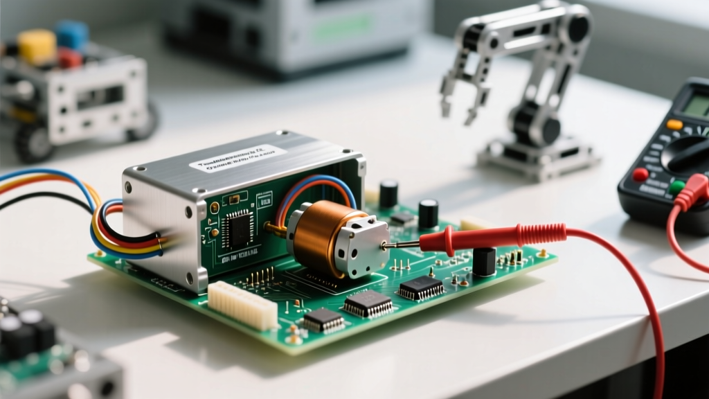
Pro Diagnostic Tip: To measure true stall current safely, lock the motor shaft using a pair of insulated pliers, set your multimeter to the 10A fused setting, and place it in series with the motor. Apply power for no more than 2 seconds to prevent the windings from melting.
Symptom 2: Microcontroller Resets Upon Motor Startup
If your Arduino or ESP32 randomly reboots the moment the motor engages, you are experiencing a brownout caused by either inductive kickback (Back-EMF) or power rail collapse.
Managing Back-EMF and Ground Loops
When a DC motor spins, it acts as a generator. When you abruptly cut power via the driver IC, the collapsing magnetic field generates a massive reverse voltage spike (Back-EMF). If your driver lacks adequate flyback diodes, or if you are sharing a noisy ground plane between the motor power and the microcontroller logic, this spike will couple into the MCU's reset pin or VCC rail.
- The Fix: Ensure your driver board has Schottky flyback diodes (like the 1N5819) installed across the motor terminals. Standard 1N4007 rectifier diodes are often too slow to catch the nanosecond spike.
- Decoupling: Place a bulk electrolytic capacitor (e.g., 470µF to 1000µF) directly across the motor driver's main power input terminals to act as a local energy reservoir. Add a 0.1µF ceramic capacitor across the motor's physical terminals to suppress high-frequency brush noise.
- Star Grounding: Never daisy-chain your grounds. Connect the MCU ground, driver logic ground, and high-current power ground to a single, central "star" point to prevent high-current return paths from altering the MCU's ground reference.
Symptom 3: Erratic Speed Control and PWM Jitter
If your motor stutters at specific PWM (Pulse Width Modulation) duty cycles or runs hotter than expected, you likely have a logic level mismatch or a switching frequency issue.
The 3.3V vs. 5V Logic Level Mismatch
Many legacy drivers, such as the ubiquitous L298N, were designed for 5V TTL logic. Modern microcontrollers like the ESP32, Raspberry Pi Pico (RP2040), and STM32 output 3.3V logic. While the L298N datasheet claims a 2.0V minimum for a logic HIGH, operating a BJT-based H-bridge in the linear region due to marginal gate drive voltages causes massive internal heat dissipation and erratic switching.
According to Texas Instruments' motor driver application notes, driving a MOSFET or BJT gate without fully saturating it turns the switch into a resistor. If you must use an L298N with a 3.3V MCU, use a dedicated logic level shifter (like the TXB0106) or opt for a modern MOSFET-based driver that explicitly supports 3.3V logic thresholds.
Driver IC Comparison and Thermal Failure Modes
Choosing the wrong driver architecture is a primary cause of thermal shutdowns. Below is a diagnostic comparison of popular driver ICs to help you identify if your hardware is fundamentally mismatched to your load.
| Driver IC | Topology | Continuous Current | Voltage Drop / Rds(on) | Common Failure Mode |
|---|---|---|---|---|
| L298N | BJT H-Bridge | 2A | ~2.0V Drop | Thermal shutdown due to massive Vce(sat) losses; requires heavy heatsinks. |
| TB6612FNG | MOSFET H-Bridge | 1.2A | ~0.5Ω (0.5V @ 1A) | Melting of DIP pins if continuous current exceeds 1.5A without forced air. |
| DRV8871 | MOSFET Half-Bridge | 3.6A | ~0.55Ω | Overcurrent protection tripping during sudden direction reversals. |
| BTS7960 | MOSFET Half-Bridge | 43A | ~1.5mΩ | Logic optocoupler failure if high-current ground is not properly isolated. |
For a deep dive into selecting the right module, Pololu's comprehensive guide on motor drivers highlights how MOSFET Rds(on) values drastically alter battery life and thermal management in mobile robots compared to older BJT designs.
Step-by-Step Multimeter Diagnostic Protocol
When visual inspection and code verification fail, rely on your digital multimeter (DMM) to isolate the fault. Follow this exact sequence to troubleshoot your dc motor and driver setup:
- Verify Logic Highs: Disconnect the motor. Set your DMM to DC Voltage. Probe the MCU's PWM output pin while commanding a 100% duty cycle. If you read 3.3V but the driver requires 5V, you have found your bottleneck.
- Measure VCC Under Load: Connect the motor. Probe the driver's main power input terminals (not the power supply output). Command the motor to spin. If the voltage drops by more than 10%, your power supply is inadequate, or your wiring gauge is too thin (e.g., using 24 AWG breadboard wires for a 5A load).
- Check the Enable Pin: Many beginners forget to pull the driver's ENABLE pin HIGH. Measure the voltage at the EN pin. If it is floating or LOW, the internal H-bridge logic gates will remain closed, regardless of your PWM signals.
- Test for Inductive Shorts: Set your DMM to continuity/diode mode. Disconnect all power. Probe across the motor terminals. You should read a very low resistance (often 1Ω to 10Ω). If you read infinite (OL), the internal carbon brushes are worn out or the thermal fuse inside the motor casing has blown.
Conclusion: Designing for Robustness
Troubleshooting a dc motor and driver circuit is ultimately an exercise in respecting the laws of physics. By ensuring proper logic level translation, providing adequate bulk capacitance to handle stall currents, and utilizing star-grounding topologies to protect sensitive microcontrollers, you can eliminate 95% of common electromechanical failures. Always consult your specific driver IC's datasheet for absolute maximum ratings and thermal resistance metrics before finalizing your PCB or breadboard layout.