
The Hidden Anatomy: How Are Breadboards Connected Internally?
Solderless breadboards are the cornerstone of electronics prototyping, allowing engineers and hobbyists to build circuits without committing to permanent solder joints. However, to design safe and reliable prototypes, you must first understand the hidden internal topology of these boards. When beginners ask, 'how are breadboards connected?', they are usually referring to the invisible network of metal spring clips hidden beneath the plastic housing.
Standard breadboards are built on a 0.1-inch (2.54 mm) pitch grid. Beneath the surface, phosphor bronze or beryllium copper spring clips grip the inserted component leads. These clips are arranged in two distinct functional zones: the terminal strips and the power rails.
The Terminal Strips and the DIP Trench
The main working area of a breadboard consists of terminal strips. Each row contains five holes that are internally connected by a single metal clip. This specific 5-hole grouping is designed to accommodate Dual In-line Package (DIP) integrated circuits. When you straddle an IC across the center trench (the DIP gap), the pins on one side connect to rows 1-5, and the pins on the other side connect to rows 6-10, preventing immediate short circuits across the chip.
The Power Rails
Running vertically along the edges of the board are the power rails, typically marked with red and blue lines. Unlike the terminal strips, these rails are connected in continuous columns spanning the entire length of the board. However, a critical safety trap exists here: on many modern mid-sized breadboards, the power rails are split in the middle. Assuming a continuous connection across a split rail is one of the most common causes of unpowered microcontrollers and erratic sensor behavior.
| Zone | Internal Connectivity | Primary Use Case | Safety Hazard if Misused |
|---|---|---|---|
| Terminal Strip (Rows A-E) | 5 holes connected horizontally | Component placement, signal routing | Shorting adjacent IC pins |
| Terminal Strip (Rows F-J) | 5 holes connected horizontally | Component placement, signal routing | Shorting adjacent IC pins |
| Center DIP Trench | No internal connection (Isolation) | Straddling ICs and optoisolators | None (Physical barrier) |
| Power Rails (Red/Blue) | Continuous vertical columns (often split at center) | VCC, VDD, GND distribution | Assuming continuity across split gaps |
The Physics of Contact Resistance and Thermal Runaway
Understanding how breadboards are connected is only half the battle; understanding the electrical limits of those connections is where safety begins. Breadboards are notoriously poor conductors compared to soldered copper traces. The spring-clip mechanism introduces contact resistance.
On a brand-new, high-quality breadboard, contact resistance typically ranges from 10 to 50 milliohms per connection. However, as the board ages, or if oversized wires are inserted, the beryllium copper clips stretch and lose their tensile spring force. Contact resistance can easily degrade to 1 ohm or more.
The 1-Amp Rule and I²R Heating
According to Joule's first law, power dissipated as heat is calculated as P = I²R. If you push 2 Amps through a worn breadboard connection with 0.5 ohms of resistance, you generate 2 Watts of heat at a single microscopic contact point. The standard ABS (Acrylonitrile Butadiene Styrene) plastic used in breadboard housings has a glass transition temperature of around 105°C (221°F). Localized heating will soften the plastic, causing the spring clip to shift, increasing resistance further, and creating a thermal runaway loop that can melt the board or ignite nearby components.
Best Practice: Never exceed 1 Amp of continuous current through a single breadboard terminal strip. For high-current paths (like motor drivers or high-power LEDs), bypass the breadboard entirely and use direct soldered connections or heavy-gauge terminal blocks.
Wire Gauge Selection: Preventing Mechanical Damage
The physical dimensions of your jumper wires directly impact the long-term safety and reliability of the internal connections. The standard hole diameter on a solderless breadboard is designed specifically for 22 AWG (0.64 mm) solid core wire.
- 22 AWG Solid Core: The ideal standard. It provides enough surface area for the spring clip to grip without permanently deforming the metal.
- 20 AWG Solid Core: Too thick (0.81 mm). Inserting 20 AWG wire will permanently stretch the beryllium copper clips. Once stretched, the clip will never securely hold a standard 22 AWG wire again, leading to intermittent connections and arcing.
- Stranded Wire: Highly discouraged for direct breadboard insertion. The individual strands fray, bend, and break off inside the housing. These loose copper strands can migrate between adjacent clips, causing hidden short circuits that are nearly impossible to diagnose without disassembling the board.
If you must use stranded wire for a high-current connection, solder a 22 AWG solid core 'leader' to the tip, or use specialized crimped breadboard jumper pins.
Voltage Limits, Arcing, and Creepage Safety
While most hobbyist circuits operate safely at 3.3V, 5V, or 12V, breadboards are frequently pushed into higher voltage territories for power supply prototyping or audio amplifiers. This introduces severe safety hazards related to creepage and clearance distances.
The 0.1-inch (2.54 mm) pitch of a breadboard leaves an air gap of roughly 1.5 mm between adjacent conductive clips. According to Paschen's Law and standard IPC-2221 PCB clearance guidelines, 1.5 mm of air can reliably isolate up to about 30VDC in a clean, dry environment. However, breadboards are inherently dirty environments. Flux residue, finger oils, dust, and humidity accumulate on the plastic surface, drastically lowering the surface resistivity.
The Mains Voltage Hazard
Never use a standard solderless breadboard for prototyping mains voltage (120VAC / 230VAC) or high-voltage DC (like tube amplifiers or CRT flyback transformers). At 120VAC, the peak voltage exceeds 160V. The 1.5 mm air gap is insufficient to prevent arcing, especially if humidity is present. Furthermore, the exposed metal spring clips pose a severe lethal shock hazard. For any voltage exceeding 48VDC or 30VAC, transition to a soldered perfboard, a custom PCB, or properly enclosed terminal strips.
Best Practices for Safe Power Distribution
How you route power across the breadboard dictates the stability of your entire circuit. Daisy-chaining high-current components along a single power rail causes significant voltage drops due to the cumulative contact resistance of the rail clips.
Implement Star Grounding on Breadboards
Instead of routing ground from the microcontroller to the sensor, then to the motor driver, use a 'star grounding' topology. Designate a central ground hub (a dedicated row on the terminal strip) and route individual ground wires from the hub to each component. This prevents high-current ground return paths from injecting noise into sensitive analog sensor grounds.
Multiple Power Injection Points
For boards longer than 30 rows, inject power at both the top and bottom of the power rails. This effectively halves the resistance of the power delivery network and prevents the far end of the board from experiencing brownouts during high transient current draws (such as when a servo motor stalls).
Troubleshooting Intermittent Connections and Heat
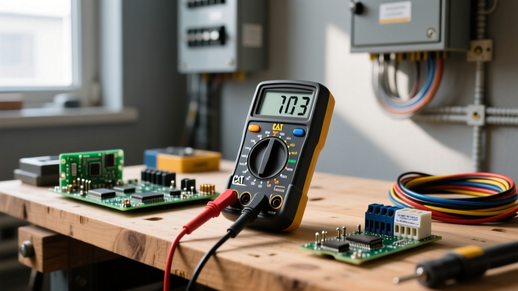
When a circuit behaves erratically, the breadboard connections are the prime suspect. Do not rely on visual inspection; the failure modes are entirely internal. Instead, use a digital multimeter (DMM) to perform a voltage drop test.
Set your DMM to the millivolt (mV) range. With the circuit powered and under load, place the probes on either side of a suspected breadboard connection (e.g., from the component lead to the jumper wire inserted in the same row). A healthy connection should show a voltage drop of less than 5mV. If you measure 50mV or higher, the internal spring clip is oxidized, stretched, or failing. If the plastic around the connection feels warm to the touch, immediately power down the circuit—the connection is in thermal runaway and poses a fire hazard.
For further reading on prototyping safety and internal board structures, refer to SparkFun's comprehensive Breadboard Tutorial and the community-driven safety analyses on Electronics StackExchange regarding maximum current limits. Additionally, Circuit Basics offers excellent visual breakdowns of internal clip degradation over time. Mastering how breadboards are connected internally transforms you from a passive assembler into a proactive, safety-conscious electronics designer.