
The Hidden Culprits: Why Conductors in a Circuit Fail
When an electrical system malfunctions, the immediate instinct is to blame the load, the power supply, or the control logic. However, the conductors in a circuit are frequently the hidden culprits. While theoretical circuit diagrams treat wires as perfect pathways with zero resistance, real-world conductors are subject to thermal cycling, mechanical fatigue, oxidation, and electromagnetic interference. Troubleshooting conductors requires shifting your mindset from viewing wires as mere 'pipes' for electricity to understanding them as complex components with specific resistance, inductance, and thermal limits.
According to ECM Web: Mastering Voltage Drop Diagnostics, a significant percentage of intermittent electrical failures in industrial and residential settings stem from degraded conductors or compromised terminations. This guide provides a comprehensive, expert-level framework for diagnosing and resolving conductor faults, ensuring your circuits operate safely and efficiently.
The 'Continuity Trap' in Circuit Diagnostics
The most common mistake DIYers and junior technicians make when troubleshooting conductors is relying solely on the continuity beep of a standard Digital Multimeter (DMM). This is known in the industry as the 'Continuity Trap.'
A standard DMM continuity test injects a minuscule amount of current—typically less than 5 milliamps—into the circuit. If you are testing a 10 AWG stranded cable that has suffered severe flex fatigue, 40 out of the 41 internal copper strands might be severed. The single remaining strand will easily carry the 5mA test current, causing the multimeter to emit a reassuring 'beep.' However, when you reconnect the circuit and apply a 15-amp load, that single strand will act as a bottleneck. It will rapidly overheat, potentially vaporizing inside the insulation, causing a massive voltage drop, or starting an electrical fire.
How to Bypass the Continuity Trap
- Load Testing: Never trust a continuity beep on power conductors. Always test for voltage drop while the circuit is under its normal operational load.
- Micro-Ohmmeters: For critical aerospace, automotive, or industrial applications, use a micro-ohmmeter (such as the Fluke 8808A) which injects 1A to 10A of test current, instantly revealing high-resistance faults hidden within stranded bundles.
Diagnostic Arsenal: Beyond the Basic Multimeter
To effectively troubleshoot conductors in a circuit, you need tools that can measure thermal anomalies, insulation integrity, and precise resistance. Here is the professional diagnostic arsenal:
- True-RMS Digital Multimeter (DMM): A high-quality meter like the Fluke 87V is essential for measuring AC/DC voltage drops with high precision, filtering out electrical noise that might skew readings on cheaper meters.
- Infrared Thermal Imager: Tools like the Fluke TiS60+ allow you to scan wire runs and terminal blocks. A degraded conductor or a loose termination will manifest as a distinct thermal hotspot due to I²R (current squared times resistance) heating.
- Insulation Resistance Tester (Megger): For diagnosing insulation breakdown that may be causing partial short circuits to ground, a Megger applies high voltage (250V to 1000V) to stress the dielectric barrier, revealing faults that a standard DMM cannot detect.
- Time Domain Reflectometer (TDR): For long cable runs (e.g., underground feeder cables or long communication lines), a TDR sends a pulse down the conductor and measures the reflection, pinpointing the exact distance to a break or short circuit.
Step-by-Step Troubleshooting Workflow for Circuit Conductors
Phase 1: Visual, Mechanical, and Thermal Inspection
Before connecting any test equipment, perform a rigorous physical inspection. Look for insulation embrittlement, which indicates chronic overheating. Check for galvanic corrosion—a green or white powdery residue at termination points, which occurs when dissimilar metals (like copper and aluminum) are joined without proper dielectric grease. Gently wiggle the conductors near terminals; if the wire moves independently of the lug, the crimp has failed mechanically.
Phase 2: Voltage Drop Under Load Testing
As recommended by Fluke's Guide to Voltage Drop Troubleshooting, voltage drop testing is the gold standard for evaluating conductor health. The National Electrical Code (NEC) suggests a maximum voltage drop of 3% for branch circuits and 5% overall for feeder and branch circuits combined to ensure reasonable efficiency.
The Math in Practice:
Consider a 12 AWG copper wire circuit with a 50-foot one-way run (100 feet total loop) carrying a 15A load. The resistance of 12 AWG copper is approximately 1.588 ohms per 1,000 feet.
V_drop = Length (ft) × Current (A) × Resistance per ft
V_drop = 100 × 15 × 0.001588 = 2.38V.
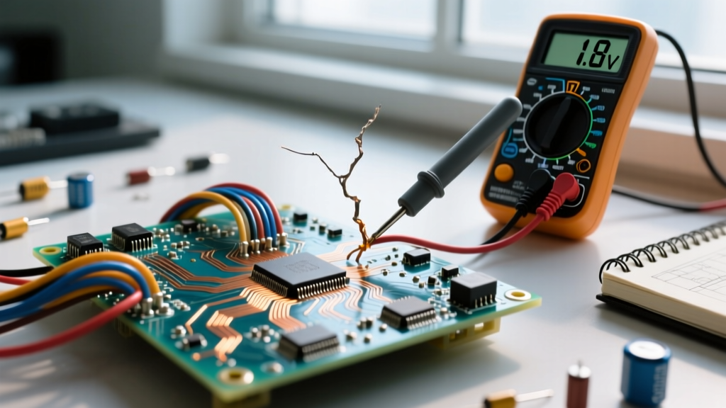
On a 120V system, a 2.38V drop (roughly 2%) is acceptable. However, if your multimeter reads a 10V drop, you have isolated the fault: the conductor is undersized, the run is too long, or more likely, there is severe oxidation at a termination point adding parasitic resistance.
Common Conductor Faults and Their Electrical Signatures
Understanding the specific signatures of conductor failures allows for rapid diagnosis. Refer to the troubleshooting matrix below:
| Fault Type | Visual / Thermal Symptom | Multimeter Signature | Real-World Scenario |
|---|---|---|---|
| Strand Fatigue (Breakage) | Insulation intact; localized heat at flex point | Passes continuity beep; high resistance under load | Robotics umbilical cables, moving machinery, audio cables |
| Galvanic Corrosion | Green/white powdery residue at lugs | Erratic resistance; voltage drop spikes under load | Copper wire terminated to aluminum busbar without inhibitor |
| Insulation Breakdown | Discolored, brittle jacket; melted spots | Intermittent ground fault; megger test fails at 500V | Overloaded 14 AWG wire on a 20A breaker in high ambient heat |
| Terminal Creep (Aluminum) | Loose connections; arcing marks on busbars | Zero continuity after thermal cycling | Older aluminum branch wiring in residential panels without CO/ALR rated devices |
Material-Specific Failures: Copper vs. Aluminum
When troubleshooting conductors in a circuit, the base metal dictates the failure mode. Copper is highly ductile and an excellent conductor, but it is prone to work hardening. If a solid copper wire is bent back and forth repeatedly, it will snap. Furthermore, copper oxidizes over time, though copper oxide is somewhat conductive compared to other metal oxides.
Aluminum, while lighter and cheaper, presents unique troubleshooting challenges. Aluminum expands and contracts at a different rate than brass or steel terminals. Over years of thermal cycling (heating up under load, cooling down at rest), aluminum conductors can 'creep' or extrude from under terminal screws, leading to loose connections, arcing, and fires. Additionally, aluminum oxide forms almost instantly when exposed to air and is highly insulating. Troubleshooting aluminum circuits often requires re-terminating connections using specialized oxide-inhibiting compounds like Penetrox or Noalox, and ensuring all lugs are rated for aluminum (marked AL/CU).
Expert Insight: 'Never underestimate the capillary effect in stranded wire. If a stranded conductor is exposed to moisture at an outdoor termination point, water can wick deep inside the insulation jacket via capillary action between the copper strands. This leads to internal 'green rot' (copper carbonate formation) that increases resistance long before the exterior of the wire shows any sign of distress. Always use sealed, adhesive-lined heat shrink for outdoor terminations.' — Senior Master Electrician Field Notes
Preventative Measures and Best Practices
Troubleshooting is ultimately about restoring a system, but preventing conductor faults requires adherence to strict installation standards. The NFPA 70: National Electrical Code (NEC) provides the baseline for safe conductor sizing and insulation selection, but best practices go further:
- Torque Specifications: Always use a calibrated torque screwdriver or wrench when terminating conductors. 'Hand-tight' is a subjective term that leads to under-torqued (high resistance/heat) or over-torqued (damaged strands/creep) connections.
- Vibration Mitigation: In environments with heavy machinery or motors, use flexible, high-strand-count conductors and secure the cable runs with proper strain relief and cushioned clamps to prevent mechanical fatigue.
- Derating for Bundling: Remember that conductors in a circuit cannot dissipate heat effectively if tightly bundled together in a conduit. Apply NEC derating factors to ensure the wire gauge is sufficient for the reduced thermal dissipation environment.
By combining a deep understanding of electrical theory with advanced diagnostic tools, you can systematically isolate and resolve faults in circuit conductors, ensuring long-term reliability and safety for any electrical system.