
The Core Concept: What is the Force That Makes Electricity Flow?
When you connect a wire to a battery and a lightbulb illuminates, an invisible phenomenon is at work. In the realm of electrical fundamentals, voltage is precisely the force that makes electricity flow. However, calling it a "force" in the strict Newtonian sense (like gravity or friction) is a common misnomer that trips up many DIY electronics enthusiasts and junior electricians. Voltage is actually a measure of potential energy difference per unit of electric charge. To truly master wire sizing, circuit design, and component selection, you must understand how this electromotive push behaves in real-world scenarios, from microscopic electron drift to macroscopic dielectric breakdown.
According to Georgia State University's HyperPhysics, voltage is formally defined as the work done per unit charge to move a test charge between two points in a static electric field. Measured in Volts (V), one volt equals one Joule of energy per Coulomb of charge. This foundational metric dictates everything from the gauge of wire you select for a DIY solar array to the insulation thickness required for mains AC wiring.
Electromotive Force (EMF) vs. Potential Difference
Beginners often conflate Electromotive Force (EMF) with potential difference, but distinguishing between the two is critical for troubleshooting. EMF is the maximum energy provided by a source (like a chemical battery or a magnetic generator) per coulomb of charge when no current is flowing (open-circuit). Potential difference, on the other hand, is the actual energy used or dropped between two specific points in a closed circuit when current is flowing. If you measure a car battery with a multimeter while the engine is off, you are reading EMF (typically around 12.6V). If you measure it while the starter motor is cranking, you are reading potential difference under load, which might drop to 10.5V due to the battery's internal resistance.
The Water Analogy (And Where It Fails in Real Electronics)
The most common beginner explainer for voltage is the water pipe analogy: Voltage is water pressure, Current is the flow rate (gallons per minute), and Resistance is the pipe's diameter. While this helps visualize Ohm's Law (V = I × R), it completely fails to explain the actual physics of the force that makes electricity flow inside a copper conductor.
Water molecules physically travel through a pipe. Electrons, however, do not race through a wire at the speed of light. In a standard DC circuit, the actual physical movement of electrons—known as drift velocity—is astonishingly slow, often less than a millimeter per second. So why does a light turn on instantly? Because the electromagnetic field propagates through the space around the wire at near light speed, pushing all free electrons in the conductor almost simultaneously. Understanding this distinction prevents beginners from making fatal errors in high-frequency AC circuit design, where skin effect and signal propagation delay matter far more than simple DC resistance.
Expert Insight: When sizing wires for high-frequency data lines (like Cat6 Ethernet or RF coaxial cables), the "pressure" of the voltage creates electromagnetic waves that travel along the dielectric insulation, not just through the copper core. This is why the insulation material's dielectric constant is just as important as the wire gauge in high-speed communications.
Real-World Voltage Sources: A Chemistry and Physics Breakdown
The "force" is generated differently depending on the source. In DIY electronics and off-grid solar setups, chemical potential is the most common origin. Below is a practical reference chart detailing the specific EMF characteristics of common power sources you will encounter in the field.
| Power Source Type | Specific Model / Chemistry | Nominal EMF | Fully Charged (Open Circuit) | Safe Cutoff (Under Load) |
|---|---|---|---|---|
| Standard Alkaline | Duracell AA (Zinc-Manganese) | 1.50V | 1.60V | 0.80V |
| Lithium-Ion | Panasonic NCR18650B | 3.60V | 4.20V | 2.50V |
| LiFePO4 (LFP) | 12V DIY Solar Battery Pack | 12.80V | 14.60V | 10.00V |
| Lead-Acid (AGM) | Optima YellowTop (Automotive) | 12.00V | 12.80V | 10.50V |
As noted by the educational resource All About Circuits, attempting to draw current from a battery below its safe cutoff voltage doesn't just stop the flow of electricity; it actively reverses or degrades the internal chemical structure, leading to permanent capacity loss or dangerous thermal runaway in lithium chemistries.
Measuring the Push: How to Use a Multimeter for Potential Difference
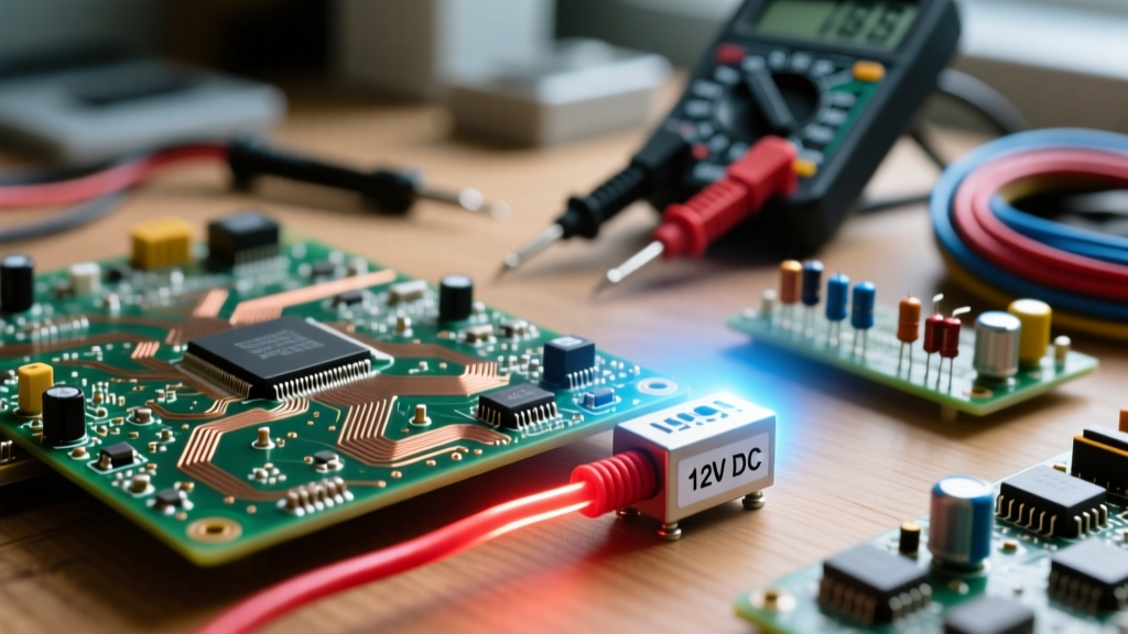
You cannot manage what you cannot measure. To verify the force that makes electricity flow in your DIY projects, a True-RMS digital multimeter (DMM) like the Fluke 117 is the industry standard. Measuring voltage is a non-intrusive parallel test, meaning you do not need to break the circuit to take a reading.
Step-by-Step Diagnostic Framework
- Set the Dial: Turn the DMM to DC Voltage (V⎓) for batteries and solar panels, or AC Voltage (V~) for household mains and inverters.
- Probe Placement: Insert the black probe into the COM (common) jack and the red probe into the V/Ω jack.
- Measure Source (EMF): Place probes directly on the power source terminals with the load disconnected. This confirms your source is healthy.
- Measure Load (Potential Difference): Keep the probes on the source terminals, but turn the load (e.g., a DC motor or LED strip) ON. If the voltage drops significantly (e.g., from 12.6V to 10.1V), you have identified excessive internal resistance or an undersized wire gauge causing a massive voltage drop.
For a comprehensive visual guide on safe measurement techniques, refer to the official Fluke voltage measurement guide, which details how to avoid arc flashes when measuring high-voltage AC panels.
When the Force Becomes Destructive: Dielectric Breakdown in Wire Insulation
Voltage is the force that makes electricity flow through conductors, but it is also the force that tries to push electricity through insulators. Every insulating material has a threshold known as its dielectric strength. If the voltage exceeds this limit, the insulating material becomes ionized and conductive, resulting in a catastrophic failure known as dielectric breakdown.
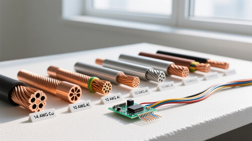
For example, standard THHN copper wire used in residential DIY wiring features a PVC and nylon insulation jacket rated for 600 Volts. If you attempt to use standard THHN wire in a DIY Tesla coil or a high-voltage DC solar string operating at 800V, the "force" will literally tear electrons away from the insulation's molecular structure. This creates a conductive plasma channel (an arc), melting the copper, igniting the PVC, and creating a severe fire hazard. This is why high-voltage DIY projects require specialized cross-linked polyethylene (XLPE) insulation rated for 2kV or higher.
Summary: Mastering the Electrical Push
Understanding voltage as the force that makes electricity flow bridges the gap between abstract physics and practical DIY application. Whether you are calculating the voltage drop across 50 feet of 12 AWG copper wire for a camper van build, diagnosing a failing LiFePO4 battery bank, or selecting the correct dielectric insulation for a custom transformer, respecting the potential difference is paramount. By moving beyond the simplistic water analogy and embracing the realities of electron drift, internal resistance, and dielectric limits, you elevate your electrical projects from dangerous guesswork to engineered precision.