
When a textbook asks, what is an alternating current, the answer is usually a simple definition: an electrical current that periodically reverses direction, typically following a sinusoidal waveform. However, for an electrical technician or electronics engineer troubleshooting a failing system, this textbook definition is woefully inadequate. In the real world, AC is a dynamic, often distorted waveform interacting with complex impedances, non-linear loads, and parasitic capacitances.
Understanding what an alternating current actually does inside a wire or across a semiconductor junction is the key to diagnosing elusive faults like unexplained breaker trips, overheated neutral conductors, and erratic microcontroller behavior. This guide moves beyond basic theory into the practical, troubleshooting-focused realities of AC circuits.
The True Nature of AC: RMS vs. Peak Voltage Anomalies
One of the most common troubleshooting pitfalls stems from a misunderstanding of how AC voltage is measured and reported. When we refer to a standard 120V AC supply, we are referring to the Root Mean Square (RMS) value, not the peak voltage. The actual peak voltage of a 120V RMS sine wave is approximately 169.7V (calculated as 120 × √2).
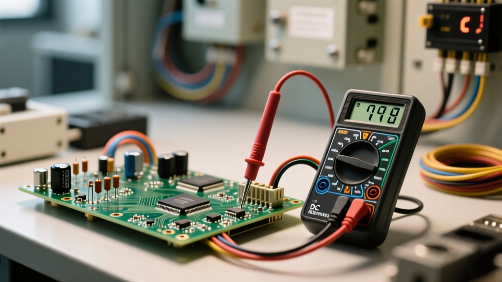
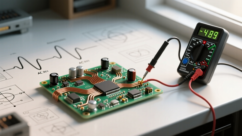
Why does this matter for troubleshooting? If you are diagnosing an insulation breakdown or a blown transient voltage suppression (TVS) diode, the component failed because it was subjected to the peak voltage, not the RMS voltage. Furthermore, if you are using an average-responding digital multimeter (DMM) to measure an AC circuit powered by a variable frequency drive (VFD) or a switched-mode power supply (SMPS), your meter will give you a dangerously inaccurate reading. Average-responding meters assume a perfect sine wave and apply a fixed scaling factor. To accurately troubleshoot modern AC circuits, you must use a True RMS multimeter capable of calculating the actual heating value of a distorted waveform.
Diagnosing Waveform Distortions and Harmonics
In an ideal world, an alternating current is a pure sine wave. In modern commercial and industrial environments, it is rarely pure. Non-linear loads—such as LED drivers, computer servers, and VFDs—draw current in abrupt pulses rather than a smooth sinusoidal curve. This introduces harmonic frequencies (multiples of the fundamental 60Hz or 50Hz frequency) onto the AC line.
The Triplen Harmonic Neutral Overheating Fault
A classic troubleshooting scenario involves a 3-phase, 4-wire wye system where the phase currents appear perfectly balanced, yet the neutral conductor is overheating or has melted. This is caused by 'triplen' harmonics (3rd, 9th, 15th). Unlike fundamental currents, which cancel out in a balanced neutral, triplen harmonic currents are in-phase and add together arithmetically. The neutral current can actually exceed the phase current by up to 173%. If you encounter an overheated neutral, clamp a power quality analyzer around the wire and look for high Total Harmonic Distortion (THD). The fix often requires upsizing the neutral conductor or installing a K-factor rated transformer designed to handle harmonic eddy currents.
The Hidden Culprit: Skin Effect in AC Wiring
When troubleshooting voltage drop or unexpected cable heating, technicians often consult wire sizing charts based on DC resistance. However, alternating current behaves fundamentally differently than direct current inside a conductor due to the skin effect. As AC frequency increases, the electromagnetic fields generated within the wire force the electrons to migrate toward the outer surface (the 'skin') of the conductor.
At standard 60Hz, the skin depth in copper is roughly 8.5mm. For smaller wires (like 12 AWG), this is negligible. But for large feeders (e.g., 500 kcmil or larger), the center of the conductor carries almost no current. This effectively reduces the cross-sectional area of the wire, increasing its AC resistance compared to its DC resistance. According to the fundamentals of AC impedance, if you are troubleshooting a severe voltage drop on a large feeder, you must use AC impedance values (which account for skin effect, proximity effect, and reactance) rather than simple DC resistance. Always reference NEC Chapter 9, Table 9 (AC Impedance) instead of Table 8 (DC Resistance) for accurate fault-finding on large AC feeders.
Troubleshooting Zero-Crossing and Phase Shift Errors
Microcontrollers, solid-state relays (SSRs), and dimmer circuits rely heavily on the 'zero-crossing' point—the exact moment the alternating current waveform passes through 0V. Zero-crossing detection is used to switch loads with minimal electromagnetic interference (EMI) and inrush current.
Troubleshooting Tip: If an SSR is misfiring, chattering, or failing to latch, do not just check the voltage magnitude. Use an oscilloscope to inspect the zero-crossing point. Inductive loads and power factor correction capacitors can introduce severe phase shifts and high-frequency ringing, confusing the zero-crossing detection circuitry. Adding an RC snubber network across the load can dampen these transients and restore clean zero-crossing signals.
AC Diagnostic Matrix: Symptoms vs. Root Causes
Use the following matrix to quickly narrow down AC-related faults in industrial and electronics troubleshooting.
| Observed Symptom | Common Root Cause | Diagnostic Tool Required |
|---|---|---|
| Neutral wire overheating despite balanced loads | High triplen harmonics from non-linear loads (SMPS, LEDs) | Power Quality Analyzer (THD measurement) |
| Insulation breakdown or TVS diode failure | Voltage transients exceeding the peak AC voltage (not RMS) | High-bandwidth Oscilloscope with differential probe |
| Unexpected voltage drop on large gauge feeders | Skin effect and AC reactance ignored during wire sizing | AC Millivolt drop test / NEC Table 9 Impedance check |
| Microcontroller resetting or SSR misfiring | Zero-crossing distortion, phase shift, or inductive ringing | Oscilloscope (Zero-crossing trigger mode) |
| Inaccurate AC voltage readings on a DMM | Using average-responding meter on a non-linear, distorted wave | True-RMS Digital Multimeter (Crest factor > 3) |
Safe Probing and Isolation Techniques for AC Faults
Troubleshooting alternating current requires strict adherence to safety protocols, particularly when moving from standard DMM measurements to oscilloscope diagnostics. A standard benchtop oscilloscope has its probe ground clip tied directly to the earth ground of the AC mains supply. If you connect this ground clip to a 'live' or 'floating' point in an AC circuit, you will create a dead short through the oscilloscope, resulting in catastrophic equipment failure and severe shock hazard.
To safely troubleshoot AC waveforms, you must use differential probes or ensure the device under test is powered through an isolation transformer. Furthermore, always verify that your DMM and test leads carry the appropriate CAT III or CAT IV safety ratings for the specific AC environment you are probing. Understanding what an alternating current is ultimately means respecting its peak potentials, its high-frequency harmonic behaviors, and the immense energy it can deliver during a fault condition.
By shifting your perspective from the idealized textbook sine wave to the complex, distorted, and impedance-driven reality of AC power, you can diagnose faults that leave other technicians baffled. Whether you are dealing with harmonic neutral overloads, skin effect voltage drops, or zero-crossing transients, mastering the true behavior of alternating current is the hallmark of an expert troubleshooter.