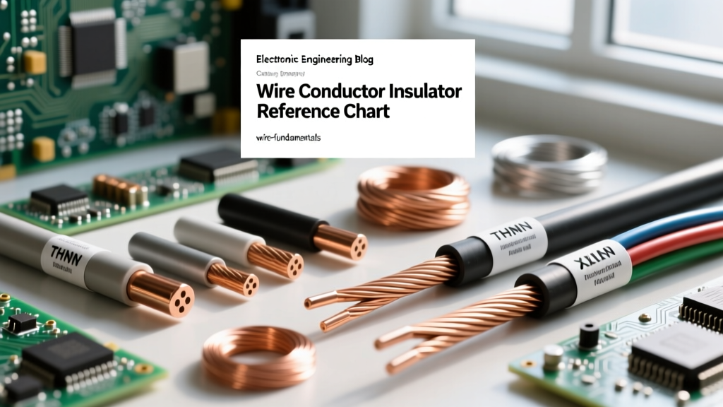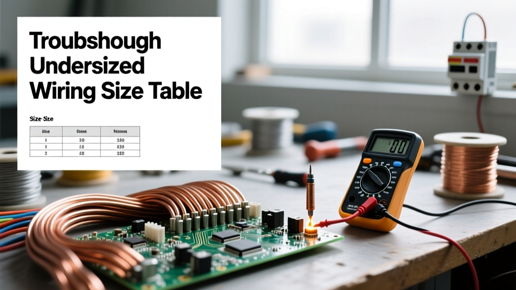

The Hidden Dangers of Ignoring the Electrical Wire Size Table
When a circuit misbehaves, the immediate instinct is often to blame the breaker, the appliance, or a loose connection. However, the root cause of many persistent electrical failures—ranging from nuisance tripping to melted terminal lugs—lies in a fundamental misunderstanding of conductor ampacity. As a troubleshooting electrician, your most critical diagnostic tool isn't just a multimeter; it is a comprehensive electrical wire size table. This chart, governed by the National Electrical Code (NEC) Table 310.16, dictates the maximum allowable current for specific wire gauges, materials, and temperature ratings. Misapplying these values during installation or troubleshooting can lead to catastrophic thermal failures.
In this guide, we will reverse-engineer common circuit failures and demonstrate exactly how to leverage an electrical wire size table to diagnose undersized wiring, voltage drop anomalies, and termination overheating.
Symptom 1: Nuisance Breaker Trips and Melted Insulation
Diagnosing Ampacity Mismatches
A frequent troubleshooting call involves a branch circuit that repeatedly trips, or worse, a receptacle that shows signs of thermal damage (brown scorch marks) without ever tripping the breaker. This paradox almost always points to an ampacity mismatch between the overcurrent protection device (OCPD) and the conductor.
Consulting the electrical wire size table reveals the baseline ampacities for copper conductors in the 60°C column: 14 AWG is rated for 15 Amps, 12 AWG for 20 Amps, and 10 AWG for 30 Amps. If a previous DIYer installed a 20A breaker on a 14 AWG circuit to 'stop the tripping,' they created a severe fire hazard. The wire will thermally degrade and melt at 18-19 Amps, but the breaker's thermal trip curve won't activate until the current exceeds 20 Amps for a sustained period.
According to NEC Article 240.4(D), small conductors (14, 12, and 10 AWG copper) have strict overcurrent protection limits of 15A, 20A, and 30A respectively, regardless of the wire's higher temperature rating column. Always verify the OCPD matches the smallest wire gauge on the entire run.
Troubleshooting Step: Use a non-contact voltage tester and a clamp meter to measure the actual peak load. If a 12 AWG circuit is pulling 22A, the wire is operating above its 20A ampacity limit. The fix is not a larger breaker; it is either load shedding or upgrading the entire run to 10 AWG.
Symptom 2: Severe Voltage Drop Under Load
Using the Table to Calculate Voltage Drop
When motors hum, fail to start, or incandescent lights dim significantly when an appliance kicks on, you are witnessing voltage drop. While the NEC recommends a maximum 3% voltage drop on branch circuits and 5% overall, it does not strictly enforce it as a hard rule for standard residential dwellings. However, from a troubleshooting perspective, exceeding 3% causes severe equipment wear.
To diagnose this, you must cross-reference your electrical wire size table for Circular Mils (CM). The voltage drop formula for single-phase circuits is: VD = (2 x K x I x L) / CM, where K is the resistivity constant (12.9 for Copper, 21.2 for Aluminum), I is current, and L is one-way length in feet.
| AWG Size | Circular Mils (CM) | Max Length @ 15A (120V, 3% Drop) | Max Length @ 20A (240V, 3% Drop) |
|---|---|---|---|
| 14 AWG | 4,110 | 49 feet | N/A (15A Limit) |
| 12 AWG | 6,530 | 78 feet | 157 feet |
| 10 AWG | 10,380 | 124 feet | 249 feet |
| 8 AWG | 16,510 | 197 feet | 396 feet |
Real-World Scenario: You are troubleshooting a 120V dedicated circuit for a garage refrigerator located 90 feet from the panel, wired with 14 AWG. The compressor struggles to start. Looking at the table above, 14 AWG is only viable for 49 feet at a 15A load before exceeding a 3% drop. The startup surge (LRA) causes the voltage at the receptacle to plummet below 105V, stalling the motor. The diagnostic fix requires pulling a new 10 AWG or 8 AWG circuit to compensate for the distance.
Symptom 3: Overheating at Termination Points
The 60°C vs. 75°C Column Trap
One of the most dangerous misinterpretations of the electrical wire size table involves temperature columns. Modern THHN/THWN-2 wire is rated for 90°C. An amateur might look at the 90°C column, see that 12 AWG is rated for 30 Amps, and terminate it on a 30A breaker. This is a massive code violation and a primary cause of melted breaker lugs.
NEC Section 110.14(C) dictates that the ampacity of a conductor must be selected based on the lowest temperature rating of any connected device, termination, or conductor. Most standard residential breakers, receptacles, and subpanel lugs are rated for either 60°C or 75°C. Therefore, even if your wire insulation can survive 90°C, the termination point cannot.
Troubleshooting Step: If an infrared thermometer reveals a breaker terminal running 15°F to 20°F hotter than the ambient panel temperature, the wire is likely sized using the 90°C column while the lug is limited to 60°C. You must re-evaluate the circuit using the 60°C column of the wire size table. For example, a 50A RV receptacle wired with 8 AWG THHN (rated 55A at 90°C) will overheat because the 75°C column limits 8 AWG copper to 50A, and if the termination is rated 60°C, it is limited to just 40A. The required fix is upgrading to 6 AWG copper.
Aluminum vs. Copper: The K-Factor Reality
When troubleshooting older homes or heavy feeder runs to subpanels, you will frequently encounter aluminum conductors. The electrical wire size table separates copper and aluminum into distinct columns because aluminum has a higher resistivity. In the voltage drop formula, the K-factor for copper is 12.9, while for aluminum, it jumps to 21.2. This means an aluminum conductor will experience approximately 64% more voltage drop than a copper conductor of the exact same gauge and length. Furthermore, NEC 310.10 requires that aluminum building wire must be an AA-8000 series alloy. If you are troubleshooting a subpanel feeder that is sagging in voltage and the wire is older, pre-1970s pure aluminum (AA-1350), it is highly susceptible to creep and thermal expansion at the lugs, leading to arcing. The only safe remedy is a complete replacement with modern copper or AA-8000 series aluminum, sized appropriately using the aluminum columns of the ampacity table.
Step-by-Step Troubleshooting Workflow
When arriving at a site with suspected wiring faults, follow this systematic diagnostic workflow:
- Isolate and Identify: Turn off the power and verify the physical gauge of the conductor using a wire stripper gauge or calipers. Never trust the breaker size as an indicator of wire size.
- Measure the Run: Determine the total one-way length of the circuit from the panel to the furthest outlet.
- Log the Real Load: Power the circuit and use a true-RMS clamp meter to measure the continuous current draw over a 15-minute period.
- Consult the Table: Cross-reference the measured AWG, material (Copper vs. Aluminum AA-8000), and load against the NEC Table 310.16. Apply the 60°C/75°C termination rules.
- Calculate Voltage Drop: Use the Circular Mils from the table to ensure the run length doesn't exceed the 3% threshold for the measured load.
- Thermal Scan: Use an infrared camera or thermometer to scan terminations under full load. Any hotspot indicates a lug rated lower than the conductor's ampacity or a loose mechanical connection.