
The Anatomy of a Closed-Loop DC Servo System
When engineers and advanced DIYers refer to a dc servo motor controller ic, they are typically describing a two-part ecosystem: the logic/control IC (which handles PID calculations and encoder decoding) and the power driver IC (the H-bridge that delivers current to the motor). Unlike standard open-loop DC motors, a true DC servo relies on continuous feedback. If either the logic stage or the power stage fails, the system doesn't just stop—it can oscillate violently, overheat, or destroy the motor windings.
Troubleshooting these integrated circuits requires moving beyond simple continuity checks. You must understand switching dynamics, thermal resistance thresholds, and logic-level translation. This guide provides a deep-dive diagnostic framework for identifying and resolving the most critical failure modes in modern DC servo controller ICs, including popular models like the Texas Instruments DRV8871, STMicroelectronics L6203, and legacy dedicated PID controllers like the LM629.
Essential Diagnostic Toolkit for IC-Level Troubleshooting
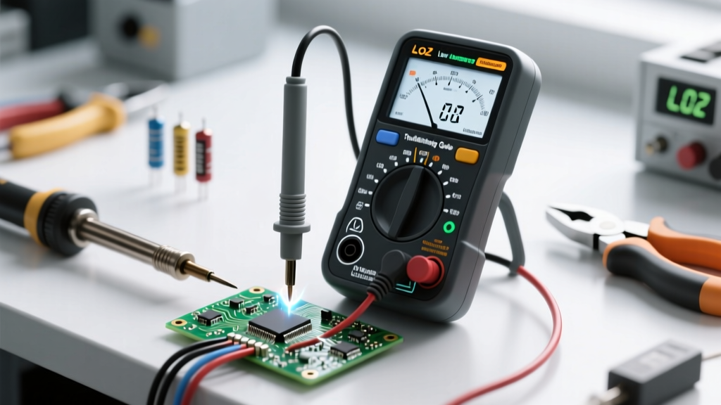
Before probing a suspected faulty servo controller IC, ensure your bench is equipped to capture high-speed transient events. A standard multimeter is insufficient for diagnosing PWM edge failures or shoot-through conditions.
- Digital Storage Oscilloscope (DSO): Minimum 100 MHz bandwidth with at least 4 channels. You need to simultaneously monitor the PWM input logic, the H-bridge output, and the quadrature encoder signals.
- Thermal Imaging Camera: Essential for identifying localized hotspots on the IC die or PCB traces that indicate internal short circuits or excessive $R_{DS(on)}$ degradation.
- Current Probe: A hall-effect current clamp to measure the actual phase current without breaking the circuit, crucial for diagnosing overcurrent protection (OCP) trips.
- Function Generator: To inject clean, isolated PWM and quadrature signals, bypassing the host microcontroller to isolate the fault to the motor driver IC.
Top 5 DC Servo Motor Controller IC Failure Modes
1. H-Bridge Shoot-Through and Cross-Conduction
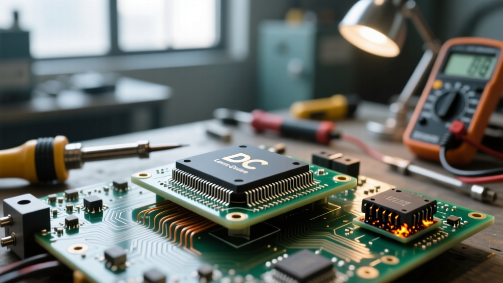
Shoot-through occurs when both the high-side and low-side MOSFETs inside the IC's H-bridge conduct simultaneously, creating a dead short across the power supply. In a dc servo motor controller ic, this is usually caused by insufficient 'dead-time' (the microsecond delay between turning one switch off and the other on) or a catastrophic failure of the internal gate driver logic.
Symptom: The IC instantly overheats upon enabling the motor, the power supply voltage sags heavily, and the system triggers overcurrent protection (OCP) before the motor can move.
Diagnostic Step: Probe the OUT1 and OUT2 pins with your oscilloscope. Zoom in on the PWM transitions. If you see overlapping voltage spikes or current draw exceeding the IC's peak rating (e.g., 3.6A for the DRV8871) during the transition edges, your dead-time is too low. Many modern ICs have internal dead-time generation, but if you are driving the gates externally or using a discrete H-bridge controller, you must increase the dead-time to at least 200ns–500ns.
2. Thermal Shutdown (TSD) Oscillation
Most modern servo driver ICs feature built-in Thermal Shutdown (TSD) circuitry. When the silicon junction temperature ($T_J$) exceeds the threshold (typically 150°C to 165°C), the IC disables its outputs. However, in poorly designed servo loops, this creates a destructive oscillation.
As the IC cools slightly below the hysteresis band, it re-enables. The motor, which is under heavy load or stalled due to a mechanical bind, immediately draws stall current, spiking the temperature back to the TSD threshold within milliseconds. This rapid on-off cycling can destroy the motor windings and degrade the IC's internal bond wires.
Diagnostic Step: Monitor the IC's fault flag pin (if available) or the current draw on your oscilloscope. If you see a periodic square wave of current draw interspersed with zero-current gaps (usually at a frequency of 1Hz to 10Hz depending on the IC's thermal mass), you are in TSD oscillation. Check the PCB's thermal vias and ensure the exposed thermal pad is properly soldered to a ground plane to lower the junction-to-ambient thermal resistance ($R_{\theta JA}$).
3. Logic-Level Translation and $V_{IH}$ Mismatches
A frequent issue in mixed-voltage systems occurs when a 3.3V microcontroller attempts to drive a 5V-tolerant or older bipolar dc servo motor controller ic. The microcontroller's 3.3V HIGH output may not meet the driver IC's minimum Input High Voltage ($V_{IH}$) specification.
For example, if an IC requires a minimum of 3.5V to register a logic HIGH, a 3.3V signal will force the internal gate drivers into their linear (active) region rather than fully saturating them. This results in massive $I^2R$ switching losses, causing the IC to overheat even under light loads.
Diagnostic Step: Measure the logic input pins with a DMM while the MCU is commanding a HIGH state. Compare this against the $V_{IH}$ parameter in the datasheet. If it's marginal, insert a dedicated logic-level translator or use a MOSFET-based level shifter to ensure crisp 5V gate drive signals.
4. PWM Frequency and Audible Noise Errors
Servo systems require precise PWM frequencies to maintain loop stability and avoid acoustic resonance. If the PWM frequency drops into the audible range (typically below 18 kHz), the motor and internal ceramic capacitors will emit a high-pitched whine. More critically, low PWM frequencies in closed-loop servos can cause torque ripple that confuses the PID tuning algorithm, leading to position hunting.
Diagnostic Step: Verify the PWM frequency generated by your MCU. For most DC servo applications utilizing ICs like the L6203 or DRV887x, a frequency between 20 kHz and 50 kHz is optimal. Frequencies above 50 kHz may cause excessive switching losses in the IC's MOSFETs, while frequencies below 16 kHz introduce audible noise and torque ripple.
5. Quadrature Encoder Desynchronization
The 'servo' aspect of the system relies entirely on the encoder. If the controller IC (or the MCU handling the PID loop) loses encoder counts due to Electromagnetic Interference (EMI) from the motor's brushes, the closed-loop system will experience 'runaway' behavior, driving the motor at 100% duty cycle in a desperate attempt to reach a target position it believes it hasn't reached.
Diagnostic Step: Route the oscilloscope probes to the encoder A and B phase lines. Command the motor to spin. If you see high-frequency ringing or voltage spikes superimposed on the clean 5V or 3.3V quadrature square waves, EMI is corrupting your feedback. Implement hardware Schmitt triggers (like the 74HC14) on the encoder inputs and use twisted-pair, shielded cabling for the encoder signals.
Component-Level Troubleshooting Matrix
| Observed Symptom | Suspect IC Stage | Diagnostic Measurement | Corrective Action |
|---|---|---|---|
| Motor stutters or vibrates at low speeds | PWM Logic / Dead-Time | Scope PWM duty cycle and output edges | Increase dead-time; check for non-linear PWM mapping |
| IC case is too hot to touch instantly | Power H-Bridge | Check for shoot-through current spikes | Add RC snubber; verify logic level $V_{IH}$ thresholds |
| Motor runs away to hard stop | Encoder Interface | Check quadrature signals for EMI noise | Add Schmitt triggers; shield encoder cables |
| System resets when motor starts | Power Supply / Decoupling | Monitor VCC rail for voltage sag | Increase bulk capacitance; separate logic and motor grounds |
| Motor brakes too aggressively, frying IC | Flyback / Clamp Diodes | Measure inductive kickback voltage spikes | Ensure internal clamp diodes are rated; add external Schottky diodes |
Preventative Circuit Design and Snubber Networks
While modern dc servo motor controller ICs include robust protection features like Overcurrent Protection (OCP), Undervoltage Lockout (UVLO), and Thermal Shutdown (TSD), relying on these features for normal operation is a hallmark of poor design. These protections are meant for catastrophic fault survival, not routine current limiting.
To maximize the lifespan of your controller IC, implement the following preventative hardware designs:
- RC Snubber Networks: Place a series resistor and capacitor (e.g., 10Ω and 100nF) across the motor terminals. This dampens the high-frequency ringing caused by the parasitic inductance of the motor windings interacting with the IC's internal MOSFET capacitance, significantly reducing EMI and voltage overshoot.
- Star Grounding Topology: Never route the high-current motor return path through the same PCB trace as the logic ground. Use a star-grounding topology where the power supply ground, the H-bridge ground, and the MCU/Logic ground meet at a single, low-impedance point (usually the bulk capacitor).
- External Schottky Diodes: While many ICs feature internal body diodes for flyback protection, their reverse recovery time ($t_{rr}$) is often too slow for high-frequency PWM. Adding external fast-recovery Schottky diodes across the motor outputs provides a lower-resistance path for inductive kickback, keeping the heat inside the diodes rather than the IC silicon.
Authoritative References and Datasheets
For exact thermal resistance calculations, logic thresholds, and timing diagrams, always consult the manufacturer's primary documentation. The following resources are essential for advanced servo IC troubleshooting:
- Texas Instruments DRV8871 Datasheet - Comprehensive details on H-bridge timing, OCP thresholds, and thermal pad layout requirements.
- STMicroelectronics L6203 Datasheet - Excellent reference for DMOS technology, multi-pin thermal dissipation, and bootstrap capacitor sizing.
- TI Motor Driver Design Resources - Application notes covering PCB layout best practices for minimizing EMI in closed-loop DC servo systems.