
The Hidden Dangers of Enameled Transformer Wire
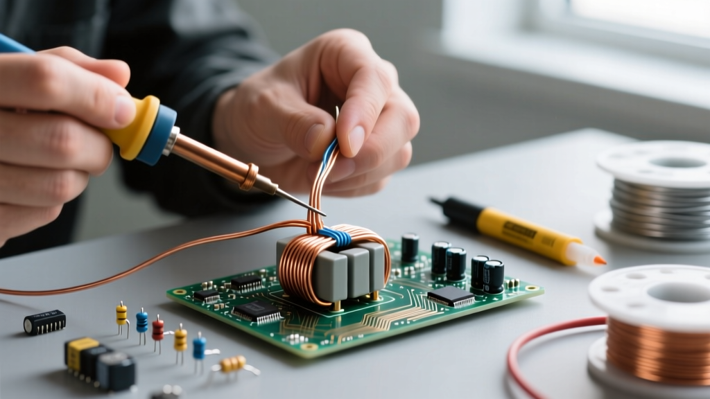
When building custom inductors, repairing audio output transformers, or rewinding switched-mode power supplies (SMPS), transformer wire (commonly known as magnet wire or enameled copper wire) is the foundational material. Unlike standard PVC-insulated hookup wire, transformer wire relies on a microscopically thin layer of polymer enamel for dielectric isolation. While this maximizes the copper fill factor in a winding window, it introduces severe safety and reliability risks if mishandled.
The most catastrophic failure mode in transformer winding is a turn-to-turn short. Because the voltage potential between adjacent turns is usually low, a micro-fracture in the enamel might not arc immediately. However, over time, thermal cycling and electromagnetic vibration cause the bare copper to rub against the adjacent turn, eventually creating a dead short. This results in localized thermal runaway, melting the bobbin, and potentially causing a fire. Understanding the material science of transformer wire is the first step in preventing these hazardous failures.
Decoding Insulation Classes and Thermal Limits
Not all transformer wire is created equal. The enamel coating is engineered to withstand specific thermal environments, categorized by NEMA (National Electrical Manufacturers Association) standards. Pushing a wire beyond its thermal class causes the enamel to become brittle, crack, and lose its dielectric strength. According to the MWS Wire Industries technical specifications, selecting the correct thermal class is critical for long-term safety.
| Enamel Type | NEMA Designation | Max Temp (°C) | Directly Solderable? | Primary Safety Hazard |
|---|---|---|---|---|
| Polyurethane (UEW) | MW 2-C / MW 82-C | 105°C - 130°C | Yes (at 380°C+) | Low thermal cutoff; melts easily during prolonged soldering. |
| Polyester (PEW) | MW 35-C | 155°C | No | Requires mechanical stripping; high risk of copper nicking. |
| Polyamide-Imide (AIW) | MW 16-C | 200°C | No | Extremely tough; chemical stripping requires hazardous solvents. |
| Polyimide (Kapton) | MW 16-C (Topcoat) | 220°C+ | No | Thermal degradation releases toxic fumes if burned off. |
Corona Inception Voltage (CIV) and Partial Discharge
In high-frequency applications like SMPS transformers, steep dV/dt waveforms can trigger partial discharge within microscopic voids in the enamel. This phenomenon, governed by the Corona Inception Voltage (CIV), slowly carbonizes the insulation from the inside out. To mitigate this, always use transformer wire with a heavy or triple-build enamel coating (e.g., MW 16-C) for high-voltage primary windings, ensuring the dielectric thickness can withstand voltage spikes without ionizing the surrounding air.
Safe Stripping Techniques: Mechanical vs. Thermal vs. Chemical
Improperly stripping transformer wire is the leading cause of latent failures. Nicking the copper conductor reduces its cross-sectional area, creating a localized high-resistance hotspot that will eventually melt under load. Furthermore, as noted by Remington Industries in their handling guides, leaving microscopic enamel residue on the termination point can result in high-resistance solder joints that overheat.
The Solder-Pot Method (Thermal Stripping)
For Polyurethane (UEW) wire, thermal stripping is the safest and most reliable method. By dipping the wire ends into a solder pot set between 380°C and 420°C for 2 to 4 seconds, the enamel vaporizes instantly while simultaneously tinning the copper. Safety Warning: This process releases toxic isocyanate fumes. You must perform thermal stripping under an active fume hood or use a dedicated benchtop smoke evacuator with a HEPA and activated carbon filter.
Chemical Stripping Safety
For high-temperature wires like Polyamide-Imide or Polyimide, thermal stripping will anneal and weaken the copper before the enamel burns off. Chemical stripping is required. This typically involves Dichloromethane (Methylene Chloride) based strippers. CRITICAL SAFETY PROTOCOL: Methylene Chloride is a severe health hazard and a known carcinogen. Never use chemical strippers on an open bench. They require a certified chemical fume hood, heavy-duty nitrile gloves (standard latex will dissolve), and chemical splash goggles. If you are a hobbyist without access to a fume hood, rely on meticulous mechanical stripping using a specialized thermal wire stripper tool instead.
Mechanical Stripping Best Practices
If you must strip PEW or AIW wire mechanically, never use a standard wire stripper or a utility knife. These tools shear the copper, creating stress fractures. Instead, use abrasive methods:
- Fiberglass Scratch Pens: Ideal for AWG 24 to AWG 30. They gently ablate the enamel without cutting into the copper lattice.
- Sanding Blocks: Fold 400-grit sandpaper over a flat wooden block. Pinch the wire and pull it through evenly to ensure 360-degree enamel removal without bending the conductor.
Expert Troubleshooting Tip: After mechanically stripping any transformer wire, always wipe the bare copper with isopropyl alcohol (IPA) before soldering. Enamel dust and skin oils act as barriers to flux, leading to 'cold' solder joints that appear shiny but possess high internal resistance.
Winding Tension and Layer Insulation Protocols
The physical act of winding transformer wire introduces mechanical stress. If the tension is too high, or the bend radius is too tight, the enamel will micro-crack on the outer edge of the bend. According to data from Essex Furukawa (EIS Wire), the minimum bend radius for magnet wire should generally not be less than 4 to 5 times the bare wire diameter for heavy-build enamels, and even more conservative for fine AWG wires (AWG 38+).
Inter-Layer and Outer-Wrap Insulation
Never rely solely on the wire's enamel to isolate the primary winding from the secondary winding, or to separate high-voltage layers. You must implement structural dielectric barriers.
- Mylar (PET) Tape: Use 1-mil or 2-mil thick Mylar tape between primary and secondary layers. It offers excellent dielectric strength (up to 7,000V per mil) and resists puncture from sharp wire edges.
- Nomex 410 Paper: For high-temperature or aerospace applications where Mylar might melt (Mylar degrades around 150°C), use Nomex 410 aramid paper, which withstands up to 220°C and provides superior mechanical toughness.
- Margin Tape: Always apply margin tape to the edges of the bobbin before winding. This prevents the wire from creeping into the creepage distance zone and arcing over to the adjacent pin or core.
Soldering and Termination Safety
When terminating transformer wire to a bobbin pin or a lead wire, the mechanical connection must bear the physical stress, not the solder joint. Solder is brittle and will crack under vibration or thermal expansion.
For through-hole bobbins, wrap the wire around the pin at least 1.5 to 2 times before soldering. Use a temperature-controlled soldering station set to 350°C - 380°C. Apply a high-quality rosin-activated (RA) or no-clean flux to the joint before applying heat. The flux breaks down any remaining microscopic oxides and ensures the solder wicks completely around the copper strand. Avoid holding the iron on the joint for more than 3 seconds; prolonged heat will melt the bobbin plastic (often Nylon or Phenolic) and compromise the pin's structural integrity.
Testing for Shorts and Dielectric Integrity
Before energizing any hand-wound transformer, rigorous safety testing is non-negotiable. A simple multimeter continuity test is entirely insufficient for verifying dielectric integrity.
- DC Resistance (DCR) Check: Measure the resistance of each winding. Compare it against your theoretical calculations based on AWG length. A lower-than-expected DCR indicates a hidden turn-to-turn short.
- Inductance and Q-Factor: Use an LCR meter to measure inductance. A shorted turn will drastically reduce the overall inductance and destroy the Q-factor (quality factor) of the coil.
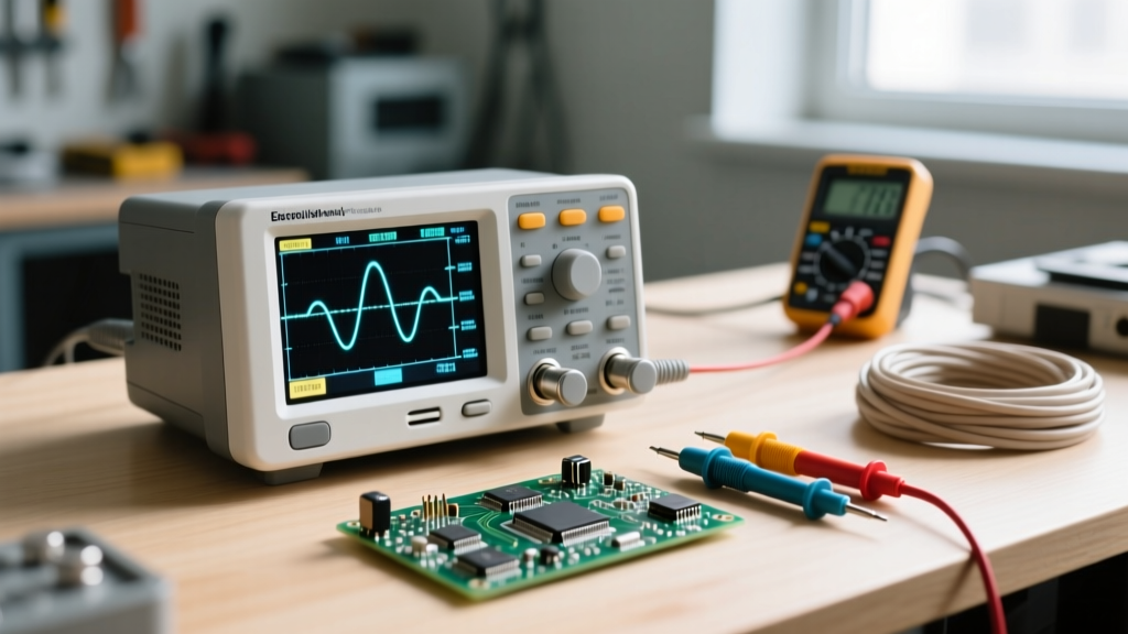
- Hipot (High Potential) Testing: For mains-voltage transformers, a Hipot test is mandatory. This applies a high DC or AC voltage (typically 1.5kV to 4kV) between the primary and secondary windings, and between the windings and the core, to verify that the insulation will not break down under fault conditions. Warning: Hipot testing involves lethal voltages and must only be performed with certified, isolated testing equipment in a controlled environment.
Summary of Best Practices
Working with transformer wire requires a shift in mindset from standard wiring practices. The insulation is fragile, the thermal limits are strict, and the consequences of a hidden defect are severe. By respecting the NEMA thermal classes, utilizing safe and precise stripping methods, enforcing strict bend-radius limits, and validating your work with proper dielectric testing, you ensure that your custom magnetics are both highly efficient and fundamentally safe.