
When designing electrical systems, selecting the correct power architecture is just as critical as choosing the right wire gauge. The debate of three phase vs single phase electricity is foundational to both residential DIY projects and heavy industrial engineering. While single-phase power dominates our homes, three-phase power is the undisputed king of manufacturing, data centers, and high-load commercial environments. Understanding the physics, wiring topologies, and copper economics of both systems will fundamentally change how you approach load calculations and conductor sizing.
The Physics: Waveforms and Phase Angles Explained
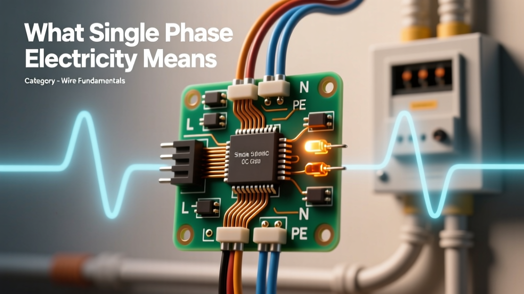
To understand the practical wiring differences, we must first look at the alternating current (AC) waveforms. Single-phase electricity operates on a single sine wave. In a 60Hz system (standard in North America), the voltage crosses zero 120 times per second. This means power delivery pulses, hitting peak capacity and dropping to zero continuously.
Three-phase electricity, however, utilizes three distinct sine waves, each offset by exactly 120 electrical degrees. Because of this phase shift, the power transfer never drops to zero. As one phase crosses the zero-voltage threshold, the other two phases are actively delivering power. This results in a remarkably smooth, constant power transfer, which is why three-phase motors run significantly cooler, experience less vibration, and boast a longer operational lifespan than their single-phase equivalents.
Single-Phase Power: Anatomy of a Residential Circuit
In the United States, what we commonly call 'single-phase' residential power is technically split-phase 120/240V. Utility companies supply a single phase to a center-tapped step-down transformer on the utility pole. This center tap creates a neutral point, yielding two 120V legs that are 180 degrees out of phase with each other.
Wiring Topology and Conductor Requirements
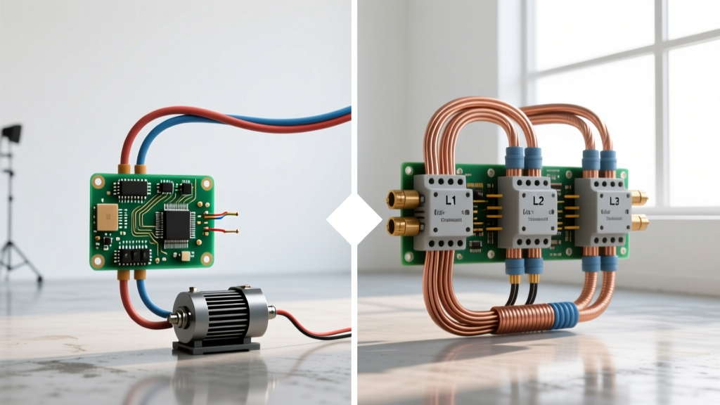
A standard split-phase system requires three wires to the main panel: Line 1 (L1), Line 2 (L2), and Neutral (N), plus an Equipment Grounding Conductor (EGC).
- 120V Circuits: Utilize one line and the neutral (e.g., lighting, standard receptacles).
- 240V Circuits: Utilize both L1 and L2 (e.g., electric ranges, HVAC compressors, EV chargers). A neutral is only added if the appliance requires 120V for control boards.
Three-Phase Power: The Industrial Workhorse
Three-phase power is generated by alternators with three separate stator windings. In commercial and industrial settings, this power is distributed via either a Wye (Star) or Delta configuration.
Wye (Star) vs. Delta Configurations
The Wye configuration features a common neutral point. In a standard 208Y/120V system, the voltage between any two phases is 208V, while the voltage from any phase to neutral is 120V. This is the standard for modern commercial office buildings, allowing heavy HVAC to run on 208V three-phase, while standard computers run on 120V single-phase.
The Delta configuration has no neutral point and is wired in a triangle. It is heavily used in manufacturing for 240V three-phase motors. Warning for DIYers and electricians: Older US commercial buildings often use a 'High-Leg Delta' (or Red-Leg Delta) system. In this setup, two phases measure 120V to ground, but the third 'high leg' measures 208V to ground. Connecting a standard 120V appliance to the high leg will instantly destroy the equipment and pose a severe fire hazard.
Head-to-Head Comparison Matrix
| Feature | Single-Phase (Split-Phase) | Three-Phase (Wye/Delta) |
|---|---|---|
| Standard US Voltages | 120V / 240V | 208V / 120V, 240V, 480Y/277V |
| Power Delivery | Pulsating (crosses zero) | Constant (smooth torque) |
| Wire Count (No Ground) | 3 Wires (L1, L2, N) | 3 or 4 Wires (L1, L2, L3, [N]) |
| Motor Efficiency | Lower, requires start capacitors | Higher, self-starting rotating field |
| Copper Cost for High Loads | High (thicker AWG required) | Low (current divided across 3 legs) |
Wire Sizing Implications: The Copper Economics
The most profound difference between three phase vs single phase electricity from a wire sizing perspective is the amount of copper required to transmit the same amount of wattage. The formula for AC power reveals why:
Single-Phase Power: P = V × I × PF
Three-Phase Power: P = √3 × V × I × PF (where √3 ≈ 1.732)
Because of the 1.732 multiplier, a three-phase system draws roughly 57.7% less current than a single-phase system to deliver the exact same power at the same voltage. Less current means smaller wire gauges, which translates to massive savings in copper costs, conduit space, and terminal sizing.
Real-World Sizing Example: 10 HP Motor at 230V
Let us size the conductors for a 10 Horsepower (HP) motor operating at 230V.
- Single-Phase 230V Motor: The NEC Full Load Current (FLC) is approximately 50 Amps. Applying the 125% continuous load rule, we size for 62.5 Amps. This requires #6 AWG THHN copper wire.
- Three-Phase 230V Motor: The NEC FLC is approximately 28 Amps. Sizing for 125% yields 35 Amps. This requires only #10 AWG THHN copper wire.
By utilizing three-phase power, you drop from #6 AWG to #10 AWG. Over a 200-foot run, this saves pounds of expensive copper and allows for much smaller, cheaper conduit.
The Voltage Drop Advantage
Voltage drop is a critical failure point in long wire runs. The multiplier for single-phase voltage drop is 2 (representing the out-and-back path of L1 and Neutral). The multiplier for three-phase voltage drop is √3 (1.732). Therefore, a three-phase circuit inherently suffers roughly 13.4% less voltage drop than a single-phase circuit using the exact same wire gauge over the same distance. For sensitive CNC machinery or long-run agricultural irrigation pumps, this 13.4% margin is often the difference between stable operation and chronic under-voltage failures.
Real-World Failure Modes and Troubleshooting
Understanding how these systems fail is vital for troubleshooting. According to power quality experts at Fluke, three-phase systems are highly efficient but vulnerable to specific asymmetrical faults.
Phase Loss (Single-Phasing)
The most destructive fault in a three-phase system is 'single-phasing.' If one fuse blows or one contactor contact fails, the motor continues to run on the remaining two phases. The motor will attempt to maintain its mechanical load by drawing massive, unbalanced current through the surviving windings. This leads to rapid insulation breakdown and catastrophic motor burnout within minutes. Troubleshooting this requires measuring voltage across all three legs simultaneously under load; a voltage imbalance of more than 2% is grounds for immediate shutdown.
Neutral Loss in Wye Systems
In a 208Y/120V system, the neutral carries the unbalanced return current. If the main neutral connection corrodes or breaks, the 120V loads on the phases will no longer be referenced to ground. Instead, they form a series circuit across the 208V phases. Lightly loaded phases will experience severe over-voltage (potentially pushing 180V+ into 120V electronics), while heavily loaded phases will brown out. Always verify neutral-to-ground voltage (which should be < 2V) when troubleshooting erratic behavior in commercial office panels.
Conclusion: Choosing the Right Architecture
The choice between three phase vs single phase electricity ultimately comes down to load density and distance. Single-phase is perfectly adequate, safe, and cost-effective for residential environments where loads are分散 (distributed) and primarily resistive or light inductive. However, once your project involves motors exceeding 5 HP, long-distance feeder runs, or high-density server racks, three-phase power becomes a mathematical necessity. By leveraging the 1.732 advantage, you drastically reduce copper requirements, mitigate voltage drop, and ensure the longevity of your heavy inductive loads. For deeper dives into NEC compliance and load balancing, always consult the latest National Electrical Code guidelines or a licensed electrical engineer.