
Decoding the American Wire Gauge (AWG) System
When navigating electrical wire sizes, the American Wire Gauge (AWG) system is the universal standard in North America. Counterintuitively, the AWG system operates on an inverse logarithmic scale: the smaller the gauge number, the larger the physical diameter and current-carrying capacity of the wire. For instance, a 4 AWG wire is significantly thicker than a 14 AWG wire.
Understanding the mathematical progression of AWG is critical for advanced electrical design. Every time you decrease the gauge by 3 (e.g., from 12 AWG to 9 AWG), the cross-sectional area—and consequently the ampacity—approximately doubles. Conversely, a drop of 10 gauge sizes (e.g., 10 AWG to 1/0 AWG) multiplies the cross-sectional area by exactly 10. This geometric progression allows electrical engineers to quickly estimate voltage drop and resistance without consulting a calculator.
Comprehensive Electrical Wire Sizes Reference Chart
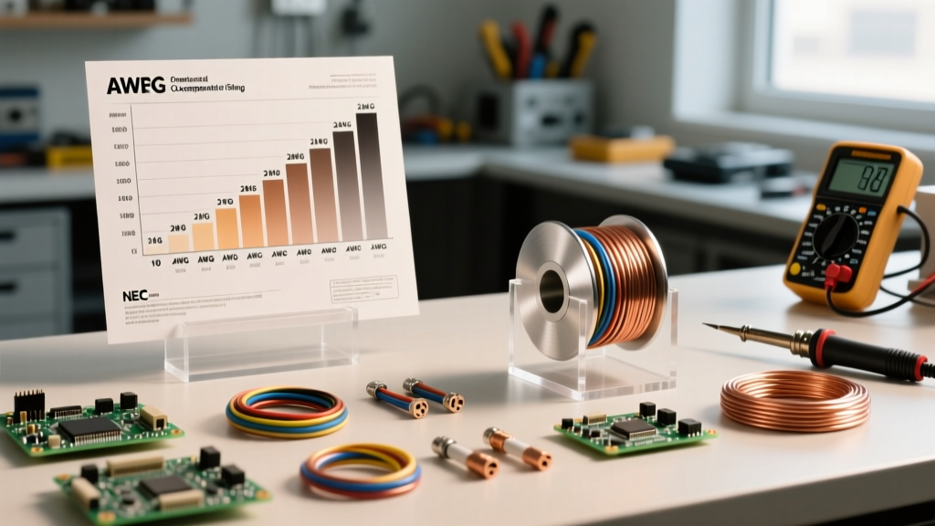
The following chart details standard solid and stranded copper electrical wire sizes, their physical dimensions, and their maximum allowable ampacities based on the National Electrical Code (NEC) Table 310.16. Always base your final breaker sizing on the lowest temperature rating of any connected component, termination, or device in the circuit.
| AWG Size | Diameter (Inches) | Area (Circular Mils) | Ampacity (60°C) | Ampacity (75°C) | Ampacity (90°C) |
|---|---|---|---|---|---|
| 14 | 0.0641 | 4,110 | 15A | - | - |
| 12 | 0.0808 | 6,530 | 20A | 25A | 30A |
| 10 | 0.1019 | 10,380 | 30A | 35A | 40A |
| 8 | 0.1285 | 16,510 | 40A | 50A | 55A |
| 6 | 0.1620 | 26,240 | 55A | 65A | 75A |
| 4 | 0.2043 | 41,740 | 70A | 85A | 95A |
| 2 | 0.2576 | 66,360 | 95A | 115A | 130A |
| 1/0 | 0.3249 | 105,600 | 125A | 150A | 170A |
| 2/0 | 0.3648 | 133,100 | 145A | 175A | 195A |
| 4/0 | 0.4600 | 211,600 | 195A | 230A | 260A |
Note: The 60°C column is generally mandated for circuits rated 100A or less, while the 75°C column applies to circuits over 100A, per NEC 110.14(C).
Copper vs. Aluminum: Ampacity and Application Differences
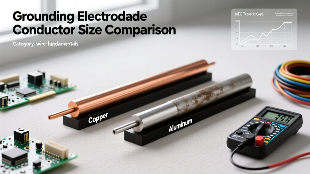
While copper is the undisputed king of residential branch circuits, aluminum wire is frequently utilized for heavy feeder lines (like 2/0 or 4/0 for 200A residential service entrances) due to its cost-effectiveness and lighter weight. However, aluminum possesses only about 61% of the conductivity of copper by volume. To carry the exact same amperage, an aluminum conductor must be sized approximately two AWG sizes larger than its copper counterpart. Furthermore, aluminum is highly susceptible to galvanic corrosion and thermal creep, necessitating the use of antioxidant compounds (like Noalox) and torque-rated terminations.
The Physics of Sizing: Circular Mils and Resistance
To truly master electrical wire sizes, one must look beyond simple AWG numbers and understand Circular Mils (CM). A mil is one-thousandth of an inch (0.001"). A circular mil is the area of a circle with a diameter of one mil. The formula to calculate the CM area of a wire is simply the diameter in mils squared (D²).
Why does this matter? Because DC resistance is inversely proportional to the cross-sectional area in circular mils. At 20°C, the approximate resistance of a copper wire per 1,000 feet can be estimated using the formula: R = 10.8 / CM. If you are designing a custom low-voltage DC harness for a solar array or an automotive application, calculating the exact CM allows you to predict voltage drop and heat dissipation with mathematical precision, preventing catastrophic insulation failure.
Additionally, in high-frequency AC applications, the 'skin effect' forces current to travel primarily on the outer perimeter of the conductor. This phenomenon makes stranded wire or specialized hollow tubing more efficient than solid core wire of the same AWG, as the effective conductive surface area is maximized.
Real-World Sizing Scenarios: Beyond the Basic Chart
Amateur electricians often size wire strictly by matching the breaker amperage to the basic chart. Professional engineers know that real-world variables demand a more rigorous approach to electrical wire sizes.
Scenario A: Long-Run Voltage Drop (Level 2 EV Charger)
Imagine you are installing a 48A Level 2 Electric Vehicle (EV) charger in a detached garage, requiring a 60A dedicated circuit. The total one-way wire run from the main panel is 150 feet. According to the 75°C column, 6 AWG copper is rated for 65A, which seems sufficient for a 60A breaker. However, pushing 48A continuous through 150 feet of 6 AWG wire results in a voltage drop of roughly 4.5%. The NEC (Article 210.19 Informational Notes) recommends keeping voltage drop under 3% for branch circuits. To maintain optimal charging efficiency and prevent the EVSE from faulting, you must upsize the wire to 4 AWG copper, dropping the voltage loss to a safe 2.8%.
Scenario B: High-Temperature Environments (Attic Feeder)
Running a 100A subpanel feeder through an unventilated attic in the middle of summer introduces severe ambient temperature derating. While THHN wire boasts a 90°C insulation rating (allowing 4 AWG to carry 95A), the attic's ambient temperature might reach 120°F (49°C). According to NEC Table 310.15(B)(1), a 90°C rated wire in a 113°F to 122°F environment must be derated to 87% of its capacity. 95A × 0.87 = 82.6A. This is no longer sufficient for a 100A breaker. You must upgrade to 3 AWG or 2 AWG copper to safely compensate for the thermal environment.
National Electrical Code (NEC) Derating Factors
When multiple current-carrying conductors are bundled together in a single conduit or cable, they cannot dissipate heat effectively. The NEC mandates strict adjustment factors to prevent the insulation from melting and causing a short circuit.
Expert Derating Rule of Thumb: If you pull 4 to 6 current-carrying conductors through a single conduit, you must multiply the wire's base 90°C ampacity by 80%. If you pull 7 to 9 conductors, the derating factor drops to 70%. Neutral conductors that only carry unbalanced current are generally not counted, but in non-linear load scenarios (like 3-phase LED lighting or VFDs), the neutral carries harmonic currents and MUST be counted as a current-carrying conductor.
Common Wire Sizing Mistakes and How to Avoid Them
- Ignoring Termination Limits: You can use 90°C THHN wire for derating calculations, but the final ampacity cannot exceed the 75°C or 60°C rating of the lugs on your breaker or receptacle. Most standard residential breakers are rated for 75°C terminations.
- Miscalculating Continuous Loads: Any load expected to run for 3 hours or more (like commercial lighting or HVAC) is considered 'continuous.' The NEC requires the circuit to be sized at 125% of the continuous load. A 20A continuous load requires a 25A minimum circuit rating, forcing you to use 10 AWG wire and a 30A breaker.
- Undersizing Grounding Conductors: The equipment grounding conductor (EGC) must scale with the overcurrent protection device. While 14 AWG is fine for a 15A or 20A circuit, a 100A feeder requires a minimum 8 AWG copper ground. If you upsize your ungrounded conductors for voltage drop, NEC 250.122(B) requires you to proportionally upsize the ground wire as well.
- Mixing Wire Metals Improperly: Pigtailing copper to aluminum using standard wire nuts is a severe fire hazard due to galvanic corrosion and differing thermal expansion rates. Always use COPALUM crimps or specialized Alumiconn connectors rated for CU/AL transitions.
For further reading on code compliance and safety standards, always consult the National Fire Protection Association (NFPA) and reference the Copper Development Association's wiring guides. For complex long-run calculations, utilizing a verified voltage drop calculator from Southwire can save you from costly material returns and failed inspections.