
When designing off-grid systems, DIY electric vehicles, or remote IoT sensor networks, selecting the right power supply is only half the battle. Equally critical is understanding how the unique electrical characteristics of different sources of direct current dictate your wiring topology, gauge selection, and safety margins. Direct Current (DC) flows unidirectionally, but the internal impedance, voltage sag, and discharge curves vary wildly depending on whether your electrons are sourced from lithium chemistry, photovoltaic cells, or thermoelectric generators.
In this comprehensive comparison guide, we will dissect the most common DC power sources used in modern DIY and professional electrical projects. We will evaluate their real-world performance, specific failure modes, and exactly how to size your conductors to minimize voltage drop and prevent thermal events.
The Physics of DC: Why Source Impedance Dictates Wire Gauge
Before comparing specific sources, we must establish a fundamental rule of DC circuit design: the internal resistance (impedance) of your power source directly impacts the allowable resistance of your wiring. Every DC source has an internal resistance ($R_i$). When a load draws current ($I$), the terminal voltage drops according to Ohm's Law: $V_{terminal} = V_{open-circuit} - (I \times R_i)$.
If you undersize your wire, you add wire resistance ($R_w$) to the circuit. The total voltage drop becomes $I \times (R_i + R_w)$. For high-impedance sources, adding thin wires will cause the voltage at the load to collapse, potentially triggering low-voltage disconnects in sensitive microcontrollers or motor controllers.
Expert Framework: Always calculate wire size using the Circular Mils (CM) formula: $CM = \frac{2 \times K \times I \times D}{VD}$, where $K$ is the resistivity of copper (12.9 ohms per mil-foot at 75°C), $I$ is current, $D$ is one-way distance in feet, and $VD$ is your target voltage drop. Never base wire sizing solely on the ampacity charts; voltage drop is the true limiting factor in low-voltage DC systems.
Electrochemical Sources: Lithium-Ion vs. LiFePO4 vs. Lead-Acid
Batteries remain the most ubiquitous sources of direct current. However, treating a Lithium-Ion (NMC) cell the same as a Lithium Iron Phosphate (LiFePO4) or Lead-Acid battery in your wiring design is a recipe for inefficiency or fire.
18650 Lithium-Ion (NMC) Cells
Cells like the Samsung 30Q or Sony VTC6 are staples in DIY power walls and e-bikes. They boast incredibly low internal resistance (typically 15mΩ to 20mΩ) and can sustain continuous discharge rates of 15A to 20A per cell. Because the source impedance is so low, the wiring must be sized to handle massive current surges without bottlenecking the pack. For a 10S4P e-bike battery pack capable of 60A continuous draw, using 12 AWG silicone wire is the absolute minimum, with 10 AWG preferred to keep the voltage drop under 3% over a 2-foot run to the motor controller.
12V LiFePO4 (LFP) Batteries
Brands like Ampere Time or Dakota Lithium offer 12V 100Ah drop-in replacements for marine and RV applications. These sources of direct current feature an integrated Battery Management System (BMS). A typical 100Ah LFP BMS is hard-limited to 100A continuous discharge. Therefore, your wire sizing must safely carry 100A indefinitely. According to standard ampacity tables, 2 AWG copper wire with 90°C insulation (like THHN) is required. Failure Mode Alert: The most common point of failure in LFP systems is the M8 terminal connection. Using open-barrel lugs instead of closed-end copper lugs with adhesive-lined heat shrink leads to oxidation, increased contact resistance, and eventual thermal melting of the battery terminal.
AGM and Gel Lead-Acid
Despite their weight, lead-acid batteries are still used in budget solar setups. They possess a much higher internal resistance than lithium alternatives. When a 100Ah AGM battery is subjected to a 50A draw, the voltage will immediately sag from 12.8V down to 11.5V or lower due to the Peukert effect and internal impedance. Because the voltage is inherently lower under load, you must oversize your DC wiring by at least one gauge compared to a lithium equivalent to prevent the load from experiencing a brownout. For a 50A draw, step up from 6 AWG to 4 AWG copper.
Photovoltaic Arrays: Sizing Wires for Solar DC Sources
Solar panels are unique sources of direct current because they act as current-limited sources rather than voltage sources. The current output ($I_{mp}$) is strictly bound by the irradiance hitting the silicon, while the voltage ($V_{mp}$) remains relatively stable until it hits the open-circuit threshold.
When wiring solar arrays, you must adhere to NEC Article 690 guidelines. The National Electrical Code requires that solar conductors be sized for 125% of the maximum short-circuit current ($I_{sc}$). Furthermore, the wire insulation must be rated for wet locations and UV exposure, making specialized PV wire (typically 10 AWG or 12 AWG stranded, XLPE insulated) mandatory for outdoor runs.
Series vs. Parallel Wiring Topologies
The way you configure your solar sources drastically alters your wire sizing requirements:
- Series Strings: Connecting three 100W panels in series increases the voltage (e.g., 54V Vmp) while keeping the current low (e.g., 5.5A). Because current is low, 10 AWG PV wire is sufficient even for 50-foot runs, as the $I^2R$ power loss remains minimal.
- Parallel Arrays: Connecting the same three panels in parallel keeps the voltage at 18V Vmp but triples the current to 16.5A. To maintain a 2% voltage drop over a 30-foot run to the charge controller, you must upgrade to 6 AWG or even 4 AWG copper, significantly increasing material costs and making physical routing into tight MC4 connectors nearly impossible without step-down pigtails.
For a deeper understanding of solar fundamentals and array configurations, the U.S. Department of Energy's Photovoltaic Basics guide provides excellent baseline data on how environmental factors affect DC output.
Niche DC Sources: Thermoelectric Generators (TEGs)
Thermoelectric generators, such as the widely available TEC1-12706 modules, utilize the Seebeck effect to convert a temperature differential ($\Delta T$) directly into DC electricity. While rarely used for high-power applications, they are vital for off-grid IoT sensors, wearable tech, and deep-space probes where solar is unavailable and batteries degrade.
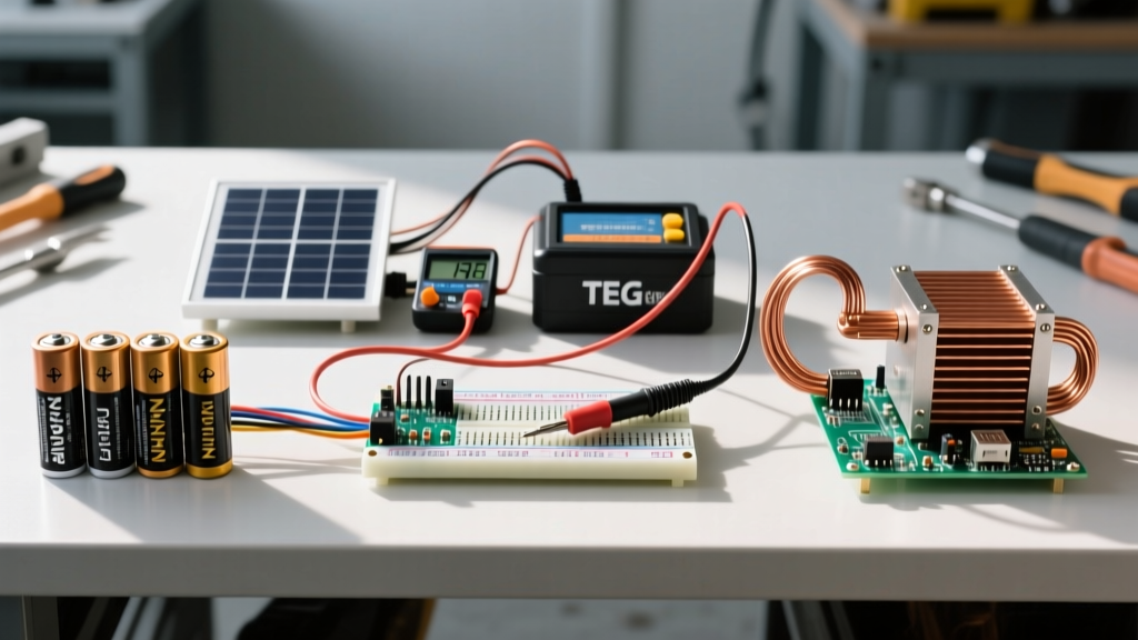
The defining characteristic of a TEG as a DC source is its exceptionally high internal resistance and ultra-low voltage output. A single module with a 50°C $\Delta T$ might only produce 1.5V at 0.3A. Because the source impedance is so high, any parasitic resistance in your wiring will completely kill the power transfer. For TEG applications, wire sizing is less about thermal ampacity and entirely about minimizing ohmic resistance. You must use the shortest possible wire runs, often soldering heavy-gauge copper pigtails directly to the module's alumina ceramic substrate before stepping down to lighter gauge wires for the sensor load.
Decision Matrix: Matching Your DC Source to the Load
Selecting the correct wire gauge and topology requires a holistic view of your DC source. Use the comparison table below to guide your next project build.
| DC Source Type | Typical Nominal Voltage | Internal Impedance | Ideal Wire Gauge (10ft, 30A) | Primary Failure Mode |
|---|---|---|---|---|
| Li-Ion (NMC 18650) | 3.6V - 3.7V per cell | Very Low (~15mΩ) | 10 AWG (Silicone) | Thermal runaway from short circuit; nickel strip bottlenecking |
| LiFePO4 12V Pack | 12.8V | Low (BMS Limited) | 4 AWG to 2 AWG (THHN) | M8 terminal oxidation; BMS thermal cutoff |
| Solar PV Array | 18V - 40V (Vmp) | Variable (Irradiance) | 10 AWG (PV Rated) | UV insulation degradation; ground fault arcs |
| Lead-Acid (AGM) | 12.0V | High (Peukert Effect) | 4 AWG (Copper) | Sulfation from voltage drop; terminal corrosion |
| TEG Module | 0.5V - 4.0V | Extremely High | 18 AWG (Short runs) | Parasitic wire resistance killing power transfer |
Safety Standards and Final Wiring Considerations
Regardless of which source of direct current you choose, safety must govern your wire sizing decisions. DC arcs are significantly more dangerous than AC arcs because there is no zero-crossing point in the voltage waveform to naturally extinguish the spark. This means that loose connections or undersized wires that overheat and melt can sustain a continuous plasma arc, leading to severe fires.
Always utilize proper overcurrent protection (fuses or DC-rated circuit breakers) placed as close to the positive terminal of the DC source as physically possible. For comprehensive safety codes governing DC wiring, refer to the NFPA 70 (National Electrical Code), specifically Articles 240 (Overcurrent Protection) and 690 (Solar Photovoltaic Systems). Additionally, for deep dives into battery chemistry safety and internal resistance metrics, Battery University remains an indispensable resource for electrical engineers and DIYers alike.
By matching your conductor size not just to the load, but to the specific internal physics of your DC source, you ensure maximum efficiency, longevity, and safety in your electrical builds.