
The NEC Framework: Why Base Ampacity is Just the Starting Point
When electricians and DIYers ask how to determine wire size, the most common mistake is looking solely at a basic ampacity chart and matching it to a breaker. However, the National Electrical Code (NEC) treats wire sizing as a multi-variable equation. Selecting the correct American Wire Gauge (AWG) requires navigating continuous load calculations, terminal temperature limitations, and environmental derating factors.
According to the National Fire Protection Association (NFPA), the NEC's primary goal is the practical safeguarding of persons and property from the hazards arising from the use of electricity. To achieve this, Mike Holt's NEC Code Articles frequently emphasize that Table 310.16 is merely the starting point. True code compliance requires adjusting that base number based on the specific physics of your installation environment.
Step-by-Step: How to Determine Wire Size for Any Circuit
To properly size a conductor, you must follow a strict sequence dictated by NEC Articles 210, 215, and 310. Skipping a step can result in undersized conductors, overheated insulation, and catastrophic arc faults.
Step 1: Calculate Continuous vs. Non-Continuous Loads
The NEC defines a continuous load as any load where the maximum current is expected to continue for three hours or more (NEC Article 100). Examples include commercial lighting, HVAC systems, and EV chargers.
- Non-Continuous Loads: Size the wire for 100% of the load.
- Continuous Loads: You must multiply the load by 125% (NEC 210.20(A)).
Real-World Example: If you are wiring a 16-Amp continuous EV charger, you cannot use a wire rated for exactly 16 Amps. You must calculate 16A x 1.25 = 20A. Your conductor must have an allowable ampacity of at least 20 Amps before any derating factors are applied.
Step 2: The Terminal Temperature Limitation Rule (110.14(C))
This is where most field inspections fail. Modern THHN/THWN-2 wire is rated for 90°C. However, NEC 110.14(C) dictates that the ampacity of a conductor is limited by the temperature rating of the equipment terminals it connects to.
Most residential breakers and receptacles are rated for 60°C or 75°C. Even if your wire insulation can withstand 90°C, you must use the 60°C or 75°C column in Table 310.16 to determine your base ampacity. The 90°C column is strictly reserved for calculating derating factors (which we cover in Step 3).
Step 3: Apply Ambient and Bundling Derating Factors
Once you have your minimum required ampacity from Step 1, you must adjust for the environment using the 90°C column of Table 310.16.
- Ambient Temperature (NEC 310.15(B)(1)): If a wire runs through an attic that reaches 110°F (43°C), you must multiply the 90°C ampacity by a correction factor of 0.87.
- Bundling (NEC 310.15(C)(1)): If you pull more than three current-carrying conductors through a single raceway, they generate mutual heat. For 4 to 6 conductors, you must derate the wire's ampacity to 80% of its 90°C value.
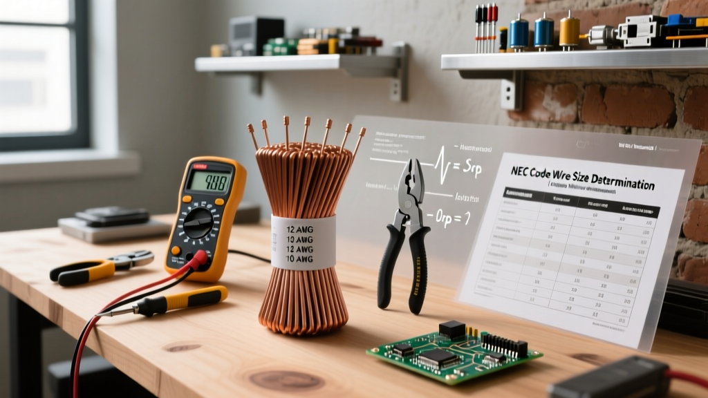
Pro Tip: After applying these derating factors, the final adjusted ampacity must still be equal to or greater than the minimum ampacity calculated in Step 1. If it falls short, you must increase the wire gauge (e.g., move from 12 AWG to 10 AWG).
Voltage Drop: The Hidden Code Recommendation
While the NEC is primarily a fire safety code, it includes Informational Notes regarding voltage drop to ensure equipment efficiency. NEC 210.19 recommends that branch circuit conductors be sized to prevent a voltage drop exceeding 3%, and the combined feeder and branch circuit drop should not exceed 5%.
NEC Informational Note: 'Conductors sized to prevent a 3 percent voltage drop will not guarantee the circuit will operate properly... but it will ensure reasonable efficiency of equipment.' For long runs, always use a dedicated calculator like the Southwire Voltage Drop Calculator to verify your gauge.
If you are running a 120V, 15-Amp circuit to a shed 150 feet away, a standard 14 AWG wire will experience a voltage drop of over 6%. To maintain the 3% threshold, you would need to upsize to 10 AWG or even 8 AWG copper, despite the breaker only requiring 14 AWG for thermal protection.
Master Wire Sizing Chart: AWG, Ampacity, and Breaker Limits
The following table outlines standard copper conductor sizing for common residential and commercial applications. Note: This assumes a standard ambient temperature of 86°F (30°C) and no more than three current-carrying conductors in a raceway.
| Wire Gauge (AWG) | Ampacity (60°C Column) | Ampacity (75°C Column) | Standard Max Breaker (240.4(B)) | Common Application |
|---|---|---|---|---|
| 14 AWG | 15 Amps | 20 Amps | 15 Amps | General lighting, standard receptacles |
| 12 AWG | 20 Amps | 25 Amps | 20 Amps | Kitchen small appliances, bathroom GFCI |
| 10 AWG | 30 Amps | 35 Amps | 30 Amps | Electric dryers, window AC units, water heaters |
| 8 AWG | 40 Amps | 50 Amps | 40 / 50 Amps | Electric ranges, EV chargers (Level 2) |
| 6 AWG | 55 Amps | 65 Amps | 60 Amps | Subpanels, tankless water heaters |
| 4 AWG | 70 Amps | 85 Amps | 70 / 80 Amps | Main service feeds, heavy HVAC compressors |
Common Code Violations and Inspector Red Flags
Even when you understand how to determine wire size mathematically, specific NEC rules restrict certain conductor sizes regardless of the calculated load. Inspectors actively look for these common violations.
The 240.4(D) Small Conductor Rule
NEC 240.4(D) places a hard, overriding cap on the overcurrent protection for small conductors. Even if your load calculation and derating math suggest you can protect a 12 AWG wire with a 25-Amp breaker, the code strictly forbids it. The limits are:
- 14 AWG: Maximum 15 Amps
- 12 AWG: Maximum 20 Amps
- 10 AWG: Maximum 30 Amps
There are specific exceptions for motor circuits and air conditioning equipment (covered in Articles 430 and 440), but for general branch circuits, these limits are absolute.
Neutral Sizing in Multi-Wire Branch Circuits (MWBC)
When sizing the grounded (neutral) conductor, NEC 220.61 requires you to calculate the maximum unbalanced load. In a standard single-phase 120/240V system, the neutral only carries the difference in current between the two hot legs. However, in environments with high harmonic distortion (like commercial offices with hundreds of LED drivers or computers), the neutral can actually carry more current than the phase conductors. In these scenarios, code requires the neutral to be sized equally to, or even larger than, the phase conductors to prevent neutral busbar fires.
Final Thoughts on Conductor Selection
Knowing how to determine wire size is a fundamental skill that bridges theoretical electrical engineering and practical field safety. Always start with the continuous load requirement, respect the terminal temperature ratings of your hardware, apply environmental derating factors, and verify voltage drop for long runs. By strictly adhering to NEC Articles 310, 210, and 240, you ensure your electrical infrastructure remains safe, efficient, and fully compliant with modern code standards.