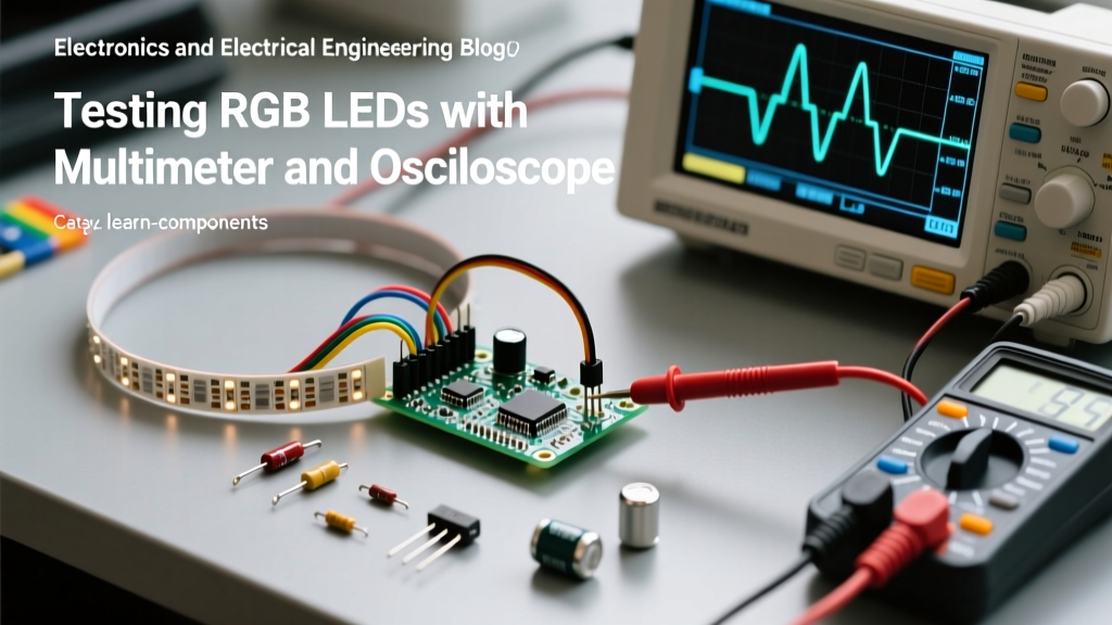

Testing and measuring RGB LEDs requires a fundamental shift in methodology depending on the component architecture. While a standard 4-pin common-cathode RGB LED relies on basic semiconductor junction testing, modern addressable RGB LEDs (such as the WS2812B or SK6812) integrate complex CMOS control circuits that demand high-speed digital signal analysis. As a prototyping engineer or DIY enthusiast, relying solely on a digital multimeter (DMM) will inevitably lead to false diagnostics and damaged components.
In this comprehensive guide, we will explore the exact testing frameworks required for both traditional and addressable RGB LEDs, utilizing multimeters, oscilloscopes, and logic analyzers to isolate failure modes, verify signal integrity, and ensure long-term reliability in your electronic projects.
The Multimeter Diode Test Trap: Why Standard RGB LEDs Fail Initial Checks
The most common mistake when prototyping with standard 5mm through-hole RGB LEDs is relying on the "diode test" mode of a digital multimeter to verify functionality across all three color channels. When you place the red probe on the anode and the black probe on the cathode, the red die will usually illuminate. However, the green and blue dies often remain completely dark, leading many hobbyists to incorrectly discard perfectly good components.
This phenomenon is rooted in the semiconductor chemistry of the LED dies and the open-circuit voltage limitations of standard multimeters. A typical DMM, such as the Fluke 87V, outputs approximately 3.5V to 4.0V on the diode test setting. Cheaper bench or pocket multimeters may only output 2.0V to 2.5V. Because the green and blue dies require a higher forward voltage to overcome their bandgap energy, a low-voltage DMM simply cannot forward-bias the junction.
"Never diagnose a blue or green LED die as 'dead' simply because it fails to illuminate during a standard multimeter diode test. Always verify the DMM's open-circuit test voltage against the LED's datasheet specifications."
Characterizing Forward Voltage and Luminous Intensity Discrepancies
To properly test and drive traditional RGB LEDs, you must understand the material science dictating their forward voltage ($V_f$). The red die is typically constructed from Aluminum Indium Gallium Phosphide (AlInGaP), while the green and blue dies utilize Indium Gallium Nitride (InGaN). This material difference creates a significant $V_f$ mismatch that complicates current-limiting resistor calculations.
| Die Material | Color | Typical $V_f$ | Max Continuous Current | Perceived Brightness at 20mA |
|---|---|---|---|---|
| AlInGaP | Red | 1.8V - 2.2V | 20mA | High (Dominant) |
| InGaN | Green | 3.0V - 3.4V | 20mA | Extremely High |
| InGaN | Blue | 3.0V - 3.4V | 20mA | Medium |
Calculating Precision Current-Limiting Resistors for 5V Logic
If you apply a single, identical resistor to all three anodes of a common-cathode RGB LED on a 5V supply, the red channel will draw significantly more current than the blue and green channels due to its lower $V_f$. This results in a washed-out, pinkish hue when attempting to mix white light.
To achieve a balanced white output, you must measure the exact $V_f$ of your specific batch using a variable bench power supply and a series milliammeter, then calculate individual resistors using Ohm's Law: $R = (V_{cc} - V_f) / I_{target}$. For a target current of 15mA on a 5V rail:
- Red (Assuming 2.0V $V_f$): $R = (5V - 2.0V) / 0.015A = 200\Omega$
- Green (Assuming 3.2V $V_f$): $R = (5V - 3.2V) / 0.015A = 120\Omega$
- Blue (Assuming 3.2V $V_f$): $R = (5V - 3.2V) / 0.015A = 120\Omega$
Debugging Addressable RGB LEDs: Oscilloscope and Logic Analyzer Tactics
The testing paradigm shifts entirely when dealing with addressable RGB LEDs like the WS2812B (NeoPixel) or SK6812. These components contain an embedded shift register and constant-current driver IC. They do not have separate anodes for colors; instead, they utilize a single digital data line (DIN) operating at 800 kHz.
According to the Adafruit NeoPixel Überguide, the data protocol relies on precise timing of high and low voltage states to represent binary 1s and 0s. A logic 1 requires a high pulse of ~0.8µs, while a logic 0 requires a high pulse of ~0.4µs. If your microcontroller's timing is off by more than ±150ns, the RGB LED will misinterpret the data, resulting in flickering, incorrect colors, or complete failure to illuminate.
Identifying Signal Degradation and the 3.3V Logic Level Failure
One of the most pervasive failure modes in addressable RGB LED prototyping is the logic voltage mismatch. The WS2812B datasheet specifies a high-level input voltage ($V_{IH}$) of 0.7 × $V_{DD}$. If you are powering the LED strip at 5V, the DIN pin requires a minimum of 3.5V to reliably register a logic HIGH.
If you are driving the data line directly from a 3.3V microcontroller (such as an ESP32 or Raspberry Pi Pico), the 3.3V output falls below the 3.5V threshold. While the first LED in the chain might marginally register the signal due to manufacturing tolerances, the signal will degrade rapidly, causing the 3rd or 4th LED in the chain to glitch.
The Measurement Solution: Connect a logic analyzer (like the Saleae Logic Pro 8) or an oscilloscope (like the Rigol DS1054Z) to the DIN line. If you observe the high-state voltage plateauing at 3.3V, you must insert a high-speed level shifter. The Texas Instruments SN74AHCT125 is the industry-standard IC for this task, as it accepts 3.3V logic inputs and outputs a clean, fast-rising 5V signal capable of driving the 800 kHz WS2812B protocol without introducing fatal propagation delays.
Power Injection and Voltage Sag Measurement in Long Data Chains
When testing large arrays of addressable RGB LEDs, visual anomalies like the strip shifting from white to red or yellow at the far end are rarely data errors; they are voltage sag issues. A single WS2812B LED drawing maximum white (all three internal dies active) consumes approximately 60mA. A strip of 60 LEDs will attempt to pull 3.6 Amps.
As detailed in the SparkFun WS2812B Hookup Guide, the thin copper traces on standard flexible printed circuits (FPC) possess significant parasitic resistance. If you measure the voltage at the microcontroller's 5V output, you may see a perfect 5.0V. However, probing the $V_{DD}$ pad of the 30th LED in the chain with your multimeter will often reveal a voltage drop to 3.8V or lower.
When $V_{DD}$ drops below 4.0V, the internal constant-current drivers of the RGB LED fail to regulate properly. Because the blue and green InGaN dies require higher forward voltages, they are the first to starve and shut down, leaving only the red AlInGaP die illuminated.
Probing the Power Rails: Best Practices
To accurately diagnose voltage sag, do not rely on the multimeter's standard DC voltage mode, which averages the reading. Instead, use an oscilloscope set to AC+DC coupling to observe transient voltage dips when the LED strip transitions from black to full-brightness white. If you observe a transient dip exceeding 0.5V, you must implement power injection. Solder heavy-gauge silicone wire (18 AWG or thicker) directly to the $V_{CC}$ and GND pads every 50 to 100 LEDs, routing the power back to a high-capacity bench supply (e.g., a Mean Well LRS-300-5).
Thermal Runaway and Luminous Decay: Stress Testing Methodologies
Finally, rigorous testing of RGB LEDs must account for thermal management, particularly in enclosed prototyping enclosures or high-density PCB matrices. As the junction temperature ($T_j$) of the LED rises, the forward voltage drops, and the luminous intensity degrades. More critically, the color wavelength shifts.
For InGaN green and blue dies, an increase in temperature typically causes a slight blue-shift in wavelength, while AlInGaP red dies experience a red-shift and a drastic drop in efficiency. If your RGB LED array is meant to produce a calibrated warm white, a 20°C rise in ambient temperature will ruin your color mixing ratios.
Stress Testing Protocol:
- Mount the RGB LED array on its intended PCB or heatsink.
- Drive the LEDs at 100% duty cycle (full white) for 60 minutes.
- Use a non-contact IR thermometer or a thermocouple epoxied to the cathode tab to measure the thermal equilibrium.
- Measure the current draw with a precision bench supply. If the current begins to climb over time without a corresponding increase in voltage, the system is experiencing thermal runaway, indicating insufficient thermal mass or a lack of PWM dimming in the firmware.
By combining low-frequency multimeter diagnostics with high-speed oscilloscope verification and rigorous thermal stress testing, you can eliminate the guesswork from RGB LED integration. Understanding the physical and electrical boundaries of both the semiconductor dies and the integrated driver ICs ensures your prototypes will transition seamlessly into reliable, production-ready hardware.