
The Anatomy of a Thumbwheel Potentiometer
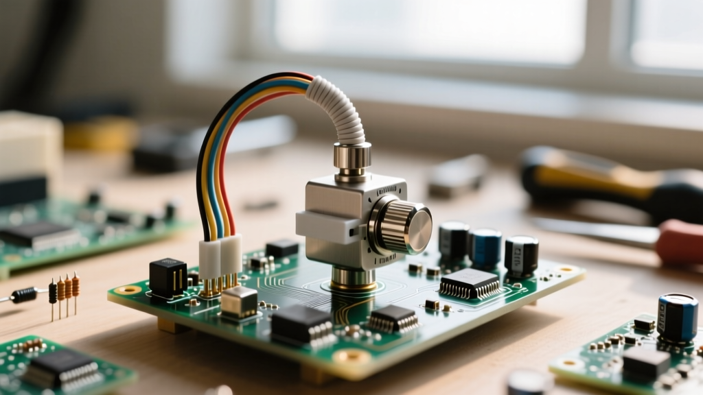
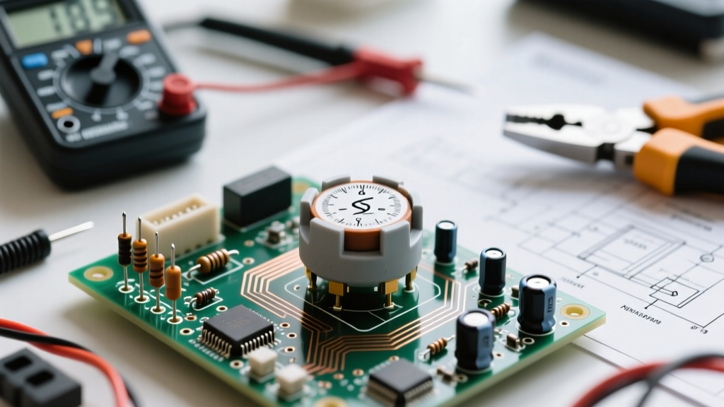
When designing precision analog circuits, aerospace instrumentation, or high-fidelity audio equipment, engineers frequently rely on a specific electromechanical component: the potentiometer wheel. Often referred to as a thumbwheel potentiometer or rotary dial trimmer, this component allows for manual, tool-free calibration in tight PCB spaces. Unlike standard slotted trimpots that require a flathead screwdriver, a potentiometer wheel features a textured, protruding dial that can be adjusted by hand.
However, from a testing and measurement perspective, these components are not immune to the inherent flaws of resistive tracking. Whether you are utilizing a cermet-based Bourns 3386 series or a Vishay T73 thumbwheel, validating the electrical and mechanical integrity of the potentiometer wheel is critical before integrating it into a production run. This guide details the rigorous testing methodologies required to evaluate linearity, contact resistance variation (CRV), and equivalent noise resistance (ENR).
Essential Tools for Potentiometer Wheel Testing
To properly characterize a potentiometer wheel, a standard digital multimeter (DMM) is insufficient. You must evaluate the component under dynamic conditions. Assemble the following test bench equipment:
- Precision DMM: A 4.5-digit or higher multimeter (e.g., Fluke 87V or Keysight 34461A) for baseline resistance and tracking tolerance.
- Digital Storage Oscilloscope (DSO): A scope with low input noise and AC-coupling capabilities (e.g., Keysight InfiniiVision) to measure microvolt-level wiper noise.
- Low-Noise DC Power Supply: To inject a stable, ripple-free test current through the resistive element.
- Precision Current-Limiting Resistors: 1% tolerance metal film resistors to create a quasi-constant current source.
- Dial Indicator or Rotary Encoder: For mapping mechanical backlash and hysteresis in geared thumbwheel models.
Step 1: Static Resistance and Tracking Tolerance Verification
The first phase of testing establishes the baseline health of the resistive track. According to the manufacturer specifications detailed in the Bourns 3386 Series Datasheet, standard cermet thumbwheels carry a total resistance tolerance of ±10%. However, for precision calibration, we must look beyond total resistance and evaluate the independent linearity.
Measuring the End-to-End Resistance
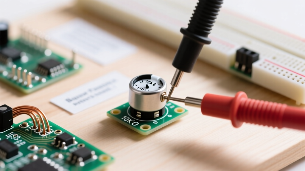
Connect your DMM probes to the two outer terminals (pins 1 and 3) of the potentiometer wheel. Record the static resistance. Next, rotate the wheel fully counter-clockwise (CCW) and measure the resistance between the wiper (pin 2) and the CCW terminal. This value represents the minimum contact resistance. Rotate fully clockwise (CW) and measure the wiper to the CW terminal.
Evaluating Tracking Tolerance
Tracking tolerance defines how closely the actual voltage divider ratio matches the theoretical mechanical rotation. To test this:
- Apply a highly stable 5.000V DC reference across the outer terminals.
- Connect the DMM to the wiper terminal.
- Rotate the potentiometer wheel in precise 10-degree increments (using a protractor jig or a geared dial fixture).
- Plot the measured voltage against the mechanical angle. Deviations exceeding ±10% of the applied voltage indicate a degraded cermet track or poor factory screening.
Step 2: Dynamic Wiper Noise and ENR Measurement
The most critical test for any potentiometer wheel used in sensitive analog signal chains is the Equivalent Noise Resistance (ENR) measurement. As the wiper slides across the cermet or carbon track, microscopic variations in the conductive material generate electrical noise. This is quantified as ENR, typically expressed in ohms.
The ENR Test Circuit
To measure ENR, we pass a known, stable DC current through the potentiometer and measure the AC noise voltage present at the wiper. The Vishay Trimmer Fundamentals Application Note outlines the standard methodology for this test:
- Configure a low-noise DC power supply to output 10V.
- Place a high-value precision resistor (e.g., 10kΩ for a 1kΩ pot, or 100kΩ for a 10kΩ pot) in series with one of the outer terminals to create a constant current source of approximately 1mA.
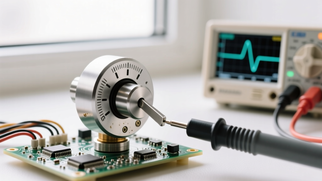
- Connect the wiper terminal to an AC-coupled oscilloscope or a low-noise preamplifier.
- Slowly rotate the potentiometer wheel through its entire mechanical range while observing the AC noise floor on the oscilloscope.
Interpreting the ENR Waveform
Calculate the ENR using the formula: ENR = V_noise(rms) / I_test. If your oscilloscope reads an RMS noise voltage of 5 microvolts (5µV) with a 1mA test current, the ENR is 5 ohms. For high-quality cermet potentiometer wheels, an ENR of less than 5 ohms is acceptable. If you observe massive voltage spikes or 'scratchy' transients during rotation, the wiper is suffering from Contact Resistance Variation (CRV) due to track oxidation, debris, or wiper lift-off.
Engineering Note: Never exceed a test current of 5mA during ENR testing. Higher currents will induce self-heating in the resistive track, altering the temperature coefficient of resistance (TCR) and yielding false noise readings due to thermal drift rather than mechanical wiper noise.
Common Failure Modes in Thumbwheel Potentiometers
Understanding how these components fail in the field is essential for designing robust test protocols. The table below categorizes the most frequent failure modes encountered during prototype validation and lifecycle testing.
| Failure Mode | Electrical Symptom | Root Cause & Prevention |
|---|---|---|
| Wiper Lift-Off | Open circuit (infinite resistance) at specific rotational angles. | Caused by mechanical shock or warped PCBs bending the component housing. Ensure proper PCB mounting hole clearances. |
| Flux Contamination | High CRV, erratic ENR spikes, and localized 'dead zones'. | Rosin or water-soluble flux wicking under the dial during wave soldering. Always use sealed variants (e.g., Bourns 'W' series) or apply Kapton tape during assembly. |
| Thermal Track Cracking | Permanent open circuit or massive localized resistance jumps. | Exceeding the 260°C for 5-seconds soldering profile limit. The ceramic substrate fractures under rapid thermal shock. |
| Wiper Wear (Carbon Tracks) | Gradual increase in baseline noise and loss of resolution. | Constant mechanical dithering in high-vibration environments. Upgrade from carbon to cermet tracks for high-reliability applications. |
Mechanical Hysteresis and Backlash Testing
While single-turn thumbwheels (like the standard 3386) rely on direct shaft friction, multi-turn potentiometer wheels utilize internal worm-gear mechanisms to translate dial rotation into fine wiper movement. This gearing introduces mechanical hysteresis, commonly known as backlash.
To test for backlash, connect the wiper to your DMM and set the component to the exact electrical center (50% resistance). Rotate the wheel clockwise by 5 degrees, then reverse direction to counter-clockwise. Measure the rotational 'dead zone'—the angle through which the dial must be turned before the electrical resistance begins to change again. In precision instrumentation, a backlash exceeding 15 degrees of mechanical rotation is generally unacceptable, as it prevents the user from reliably returning to a previously calibrated setpoint. For applications requiring zero-backlash tuning, engineers must bypass thumbwheels entirely in favor of direct-drive precision 10-turn pots with locking dials.
Pro-Tips for PCB Integration and Soldering Heat Damage
Testing a potentiometer wheel often reveals that the component was perfectly fine at the factory, but was destroyed during the PCB assembly process. Cermet tracks are surprisingly resilient, but the plastic housing and the delicate multi-finger beryllium copper wiper are highly susceptible to thermal and chemical damage.
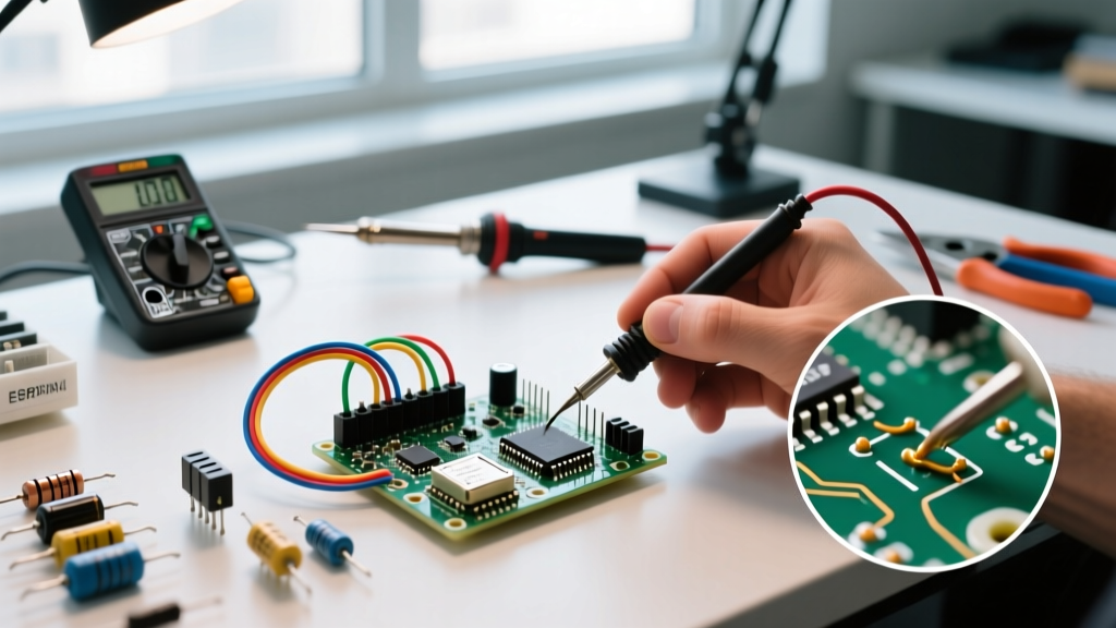
When hand-soldering prototype boards, always use a temperature-controlled iron set to a maximum of 350°C and apply heat for no longer than 3 seconds per pin. If you are utilizing an automated reflow oven, verify that the potentiometer wheel is rated for the specific reflow profile. Many standard thumbwheels are strictly designed for wave soldering or manual soldering and will melt or warp in a 245°C lead-free reflow environment.
Furthermore, as highlighted by general component theory on Electronics Tutorials, the physical placement of the potentiometer wheel on the PCB matters. Never place the component directly adjacent to high-thermal-mass ground planes without thermal reliefs, as the ground plane will act as a heat sink, drawing soldering heat away from the joint and forcing the technician to apply excessive dwell time, ultimately cooking the internal wiper mechanism.
Conclusion
A potentiometer wheel is a deceptively complex electromechanical transducer. By moving beyond simple continuity checks and implementing rigorous ENR, CRV, and mechanical backlash testing, engineers can ensure their calibration circuits remain stable, quiet, and reliable over the lifespan of the device. Whether you are tuning an RF oscillator or calibrating a medical sensor, respecting the physical and electrical limits of the thumbwheel trimmer is the hallmark of robust analog design.