
The Fundamentals of Electrical Pressure: Why Voltage Testing Matters
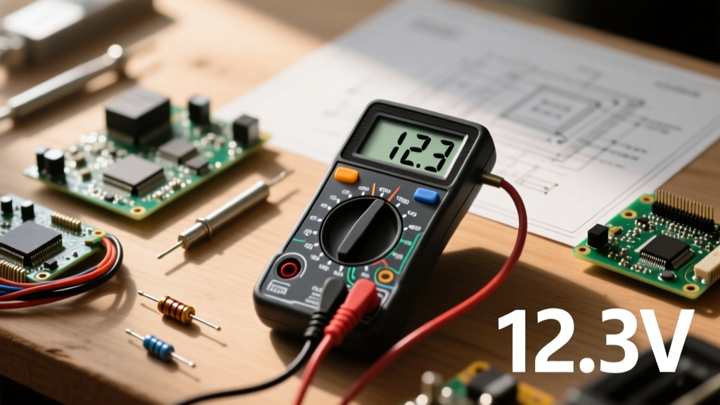
Voltage is the electromotive force, or 'electrical pressure,' that pushes current through a circuit. Whether you are diagnosing a dead car battery, troubleshooting a faulty HVAC control board, or verifying that a mains outlet is de-energized before swapping a receptacle, knowing how to test for voltage using a multimeter is the most critical skill in an electrician or electronics hobbyist's arsenal.
However, treating all voltage tests the same is a recipe for blown multimeter fuses, inaccurate readings, or worse, severe arc flash injuries. This guide breaks down the exact protocols for testing both Direct Current (DC) and Alternating Current (AC) voltage, integrating safety frameworks and professional troubleshooting techniques.
Decoding the Multimeter Dial: AC vs. DC Voltage
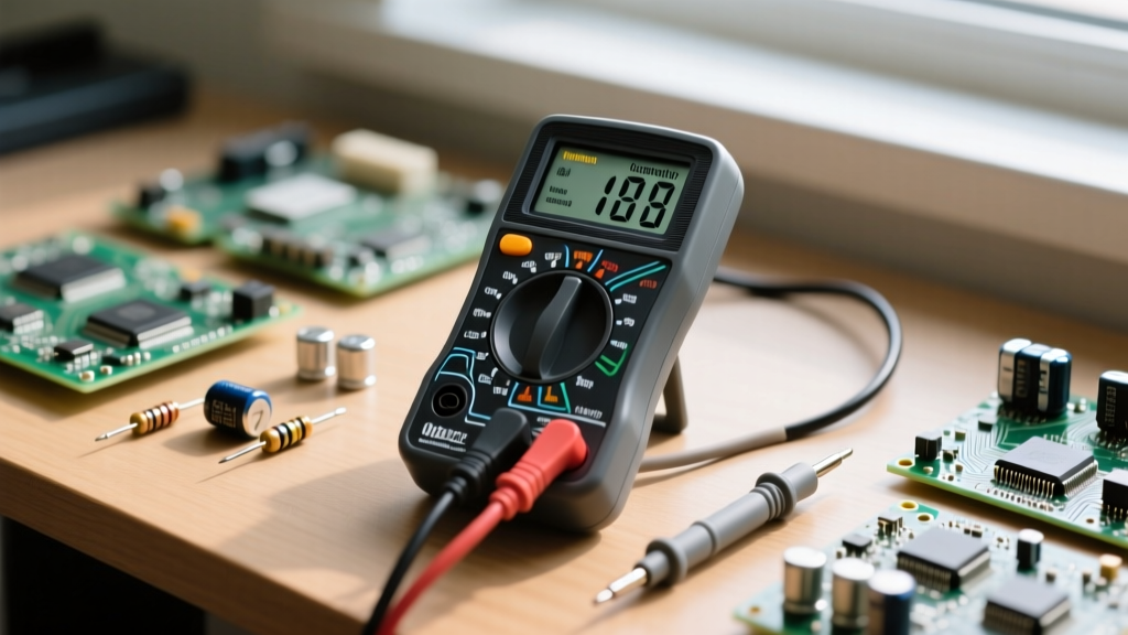
Before touching a single probe, you must configure your Digital Multimeter (DMM) correctly. Modern DMMs separate voltage testing into two distinct modes:
- DC Voltage (V⎓ or VDC): Represented by a capital 'V' with a solid straight line and a dashed line beneath it. Used for batteries, solar panels, automotive systems, and PCB logic rails.
- AC Voltage (V~ or VAC): Represented by a capital 'V' with a wavy line next to it. Used for wall outlets, household wiring, and mains-powered appliances.
Pro Tip: If your multimeter is 'auto-ranging' (like the Fluke 117 or AstroAI DM6000AR), you only need to select AC or DC. If it is 'manual-ranging,' you must also select a voltage ceiling higher than your expected reading. Testing a 120V AC outlet on the 20V manual range will result in an 'OL' (Over Limit) error and could damage the meter's internal circuitry.
The Non-Negotiable Safety Check: Probe Placement
The most common fatal error in voltage testing is leaving the red probe in the current (Amps) jack. The Amps jack utilizes a low-resistance shunt to measure current. If you insert the probes into a live voltage source while the red lead is in the Amps jack, you create a dead short. This will cause an immediate arc flash, destroy the multimeter, and potentially cause severe burns.
Always verify: The black probe must be in the COM (Common) jack, and the red probe must be in the VΩ (Voltage/Ohms) jack before testing voltage.
Step-by-Step Protocol: How to Test for DC Voltage
DC voltage flows in a single direction. Polarity matters heavily here; reversing the probes won't damage a modern DMM, but it will yield a negative reading, which can confuse beginners.
Scenario: Testing a 12V Automotive Lead-Acid Battery
- Set the Dial: Turn the DMM to DC Voltage (V⎓). If manual-ranging, select the 20V DC setting.
- Connect Probes: Black to COM, Red to VΩ.
- Test Open Circuit Voltage (OCV): Touch the red probe to the positive (+) terminal and the black probe to the negative (-) terminal.
- Interpret the Data: A fully charged, resting 12V lead-acid battery should read between 12.6V and 12.8V. If it reads 12.0V, it is only 50% charged. If it reads below 11.9V, the battery is deeply discharged or has a bad cell.
- Test Under Load (Cranking): Have a helper start the engine while you monitor the voltage. The reading should not drop below 9.6V at 70°F (21°C). A drop below this threshold indicates a failing battery or excessive parasitic draw.
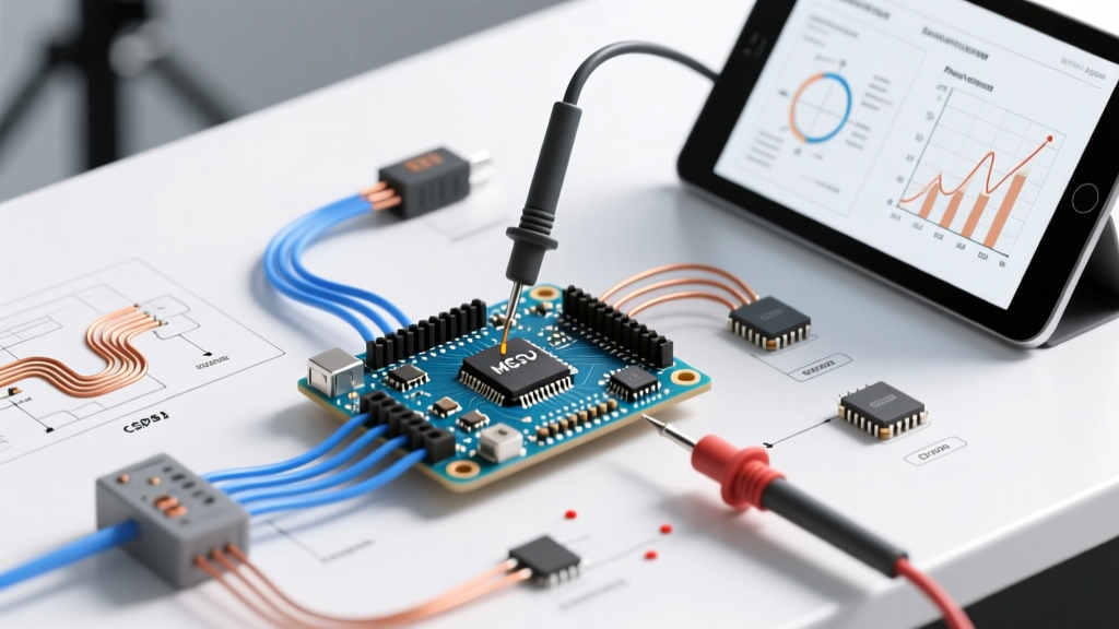
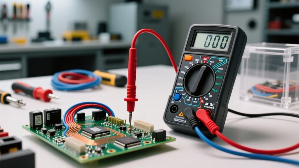
Expert Insight: When testing low-voltage DC logic boards (e.g., 3.3V or 5V Arduino rails), use needle-point probes. Standard thick DMM probes can easily bridge adjacent IC pins, shorting the microcontroller and destroying the board instantly.
Step-by-Step Protocol: How to Test for AC Mains Voltage
AC voltage constantly reverses direction, meaning polarity does not matter. You can swap the red and black probes, and the reading will remain identical. However, AC testing carries significantly higher risks due to the potential for lethal electrocution.
Scenario: Verifying a Standard US NEMA 5-15R Outlet (120V)
According to the Occupational Safety and Health Administration (OSHA), testing live circuits requires strict adherence to PPE and safe work practices. Always wear safety glasses and ensure your hands are dry.
- Set the Dial: Turn the DMM to AC Voltage (V~). Select the 200V or 600V range if manual-ranging.
- The Three-Point Test: Insert the probes into the outlet slots to perform three distinct measurements:
- Hot to Neutral (Short slot to Long slot): Should read ~120V (acceptable range: 114V - 126V).
- Hot to Ground (Short slot to U-shaped hole): Should read ~120V. This confirms the ground wire is properly bonded.
- Neutral to Ground (Long slot to U-shaped hole): Should read less than 2V. A reading higher than 2V indicates a loose neutral connection or an overloaded neutral bus bar back at the panel, which is a severe fire hazard.
The One-Hand Rule: When probing exposed AC mains terminals (like inside a breaker panel), keep one hand in your pocket or behind your back. If you accidentally touch a live conductor, this prevents the current from traveling across your chest cavity and inducing ventricular fibrillation.
Understanding CAT Ratings: Don't Ignore the Arc Flash Boundary
As detailed in Fluke's official safety guidelines, a multimeter's voltage rating (e.g., 600V) is not the whole story. You must also look at the Category (CAT) rating, which dictates the meter's ability to survive transient voltage spikes (like a nearby lightning strike or a large motor switching off).
- CAT I: Electronics, PCBs, benchtop power supplies.
- CAT II: Single-phase plug-in appliances, standard outlet receptacles.
- CAT III: Three-phase distribution, fixed wiring, breaker panels, heavy motors.
- CAT IV: Utility service entrances, overhead power lines, primary overcurrent protection.
Never use a CAT II multimeter to test voltage at a main breaker panel. A transient spike could arc across the internal PCB of the meter, causing it to explode in your hands.
The 'Ghost Voltage' Phenomenon and How to Defeat It
When testing AC voltage in multi-conductor cables (like Romex), you may measure 40V to 90V on a disconnected or 'dead' wire. This is ghost voltage, caused by capacitive coupling from adjacent live wires running in the same sheath.
Standard high-impedance digital multimeters (which typically have an input impedance of 10 Megohms) are sensitive enough to read this phantom voltage, leading technicians to mistakenly believe a circuit is still live. To solve this, use a True-RMS multimeter equipped with a LoZ (Low Impedance) mode. LoZ drops the meter's internal resistance to around 3 kilo-ohms, safely bleeding off the capacitive ghost voltage and displaying the true 0V state of the dead wire.
Pro Tool Selection Matrix for Voltage Testing
Choosing the right tool dictates your accuracy and safety. Below is a comparison of three industry-standard multimeters for voltage testing, as of current market offerings:
| Multimeter Model | CAT Rating | Key Voltage Features | Ideal User | Approx. Price |
|---|---|---|---|---|
| Fluke 117 | CAT III 600V | True-RMS, LoZ (AutoVolt), Non-Contact Voltage (NCV) | Commercial Electricians | $210 |
| Klein Tools MM400 | CAT III 600V | True-RMS, Manual/Auto ranging, Thermocouple included | Advanced DIY / HVAC Techs | $55 |
| Brymen BM235 | CAT III 600V | True-RMS, High resolution, Exceptional safety build | Electronics Engineers / EEVblog Fans | $115 |
For detailed circuit theory and foundational measurement concepts, the educational resources at All About Circuits provide excellent supplementary reading on how internal DMM shunts and voltage dividers operate.
Summary: The Voltage Testing Checklist
Mastering how to test for voltage using a multimeter requires a blend of theoretical knowledge and strict physical discipline. Before every single test, run through this mental checklist:
- Are my probes in the VΩ and COM jacks?
- Is my dial set to the correct AC or DC mode?
- Is my meter's CAT rating appropriate for the environment?
- Am I wearing appropriate PPE for the voltage level?
By respecting the electrical pressure you are measuring and utilizing the correct protocols for AC and DC systems, you ensure both the longevity of your diagnostic equipment and your personal safety.