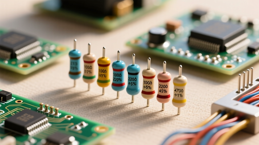

Have you ever opened a resistor assortment kit and wondered why you have plenty of 4.7kΩ and 5.1kΩ resistors, but absolutely no 5.0kΩ resistors? To the uninitiated, the available resistance values seem arbitrary and chaotic. However, the manufacturing and distribution of electronic components are governed by a strict, elegant mathematical framework known as the E-series of preferred numbers.
Understanding standard resistor values is not just an academic exercise; it is a critical skill for circuit design, Bill of Materials (BOM) optimization, and troubleshooting. In this how-it-works explainer, we will dissect the logarithmic math behind the E-series, explore why tolerance dictates the available values, and provide practical frameworks for selecting the right components for your PCB prototypes.
The Mathematical Logic Behind Standard Resistor Values
Human intuition naturally defaults to linear progression. If we were to design a resistor kit covering 1 ohm to 10 ohms using linear steps, we would include 1, 2, 3, 4, 5, 6, 7, 8, 9, and 10 ohms. But what happens when we scale up to 1 Megaohm? A linear step of 1 ohm would require one million individual physical components to cover the range. Conversely, if we used a linear step of 100,000 ohms, the gap between 1 ohm and 100,000 ohms would be practically useless for precision low-voltage circuitry.
To solve this scaling problem, electrical engineers rely on a logarithmic scale. By spacing values logarithmically, the percentage gap between any two adjacent values remains constant across all decades (e.g., 10 to 100, 100 to 1000, 10k to 100k). This ensures that whether you are designing a microamp sensor circuit or a high-voltage power supply, the relative resolution of your available components remains identical.
The IEC 60063 Standard and Logarithmic Spacing
The global authority on this system is the International Electrotechnical Commission (IEC), which formalized these values in the IEC 60063 standard. The standard defines the E-series using a geometric progression formula:
V = 10(n/N)
Where N is the number of steps per decade (the E-series number, like 12 or 24), and n is the step index (from 0 to N-1). For the widely used E12 series, N=12. The multiplier between each step is 10(1/12), which equals approximately 1.2115. Starting at 1.0, the sequence progresses as follows:
- 1.0 × 1.2115 = 1.21 (rounded to 1.2)
- 1.21 × 1.2115 = 1.46 (rounded to 1.5)
- 1.46 × 1.2115 = 1.77 (rounded to 1.8)
This mathematical rounding yields the familiar E12 sequence: 1.0, 1.2, 1.5, 1.8, 2.2, 2.7, 3.3, 3.9, 4.7, 5.6, 6.8, and 8.2. Multiply these by any power of 10, and you have the complete spectrum of standard resistor values for that series.
Decoding the E-Series: From E6 to E192
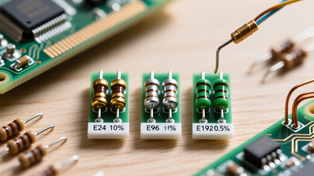
The IEC 60063 standard defines several distinct series, each tailored to specific manufacturing tolerances. The higher the number in the series, the more values exist per decade, and the tighter the manufacturing tolerance required to make the series viable.
- E3 (3 values/decade): 1.0, 2.2, 4.7. (Historically used for 40% tolerance components; largely obsolete today).
- E6 (6 values/decade): 1.0, 1.5, 2.2, 3.3, 4.7, 6.8. (Used for 20% tolerance components).
- E12 (12 values/decade): Used for 10% tolerance components.
- E24 (24 values/decade): The baseline for 5% tolerance components. This is the most common series found in hobbyist kits and general-purpose through-hole/SMD designs.
- E48, E96, E192: Used for precision components with tolerances of 2%, 1%, and 0.5% (or tighter), respectively.
Why Tolerance Dictates the Series
The most common misconception among beginners is that the E-series are just arbitrary lists of numbers. In reality, the E-series is intrinsically linked to component tolerance via the principle of overlap.
Consider the E12 series, designed for 10% tolerance resistors. Take the standard value of 4.7Ω. With a 10% tolerance, the actual resistance of a manufactured part could be as high as 5.17Ω. The next value in the E12 sequence is 5.6Ω. With a 10% tolerance, its actual resistance could be as low as 5.04Ω.
Because 5.17Ω (the high end of 4.7Ω) overlaps with 5.04Ω (the low end of 5.6Ω), there are no gaps in coverage. No matter what exact resistance you need between 4.7 and 5.6, a 10% tolerance E12 resistor will mathematically guarantee that at least one value on the production line falls within your required range.
If you were to use E12 values for 1% precision resistors, the overlap would disappear. A 4.7Ω ±1% resistor maxes out at 4.747Ω, and a 5.6Ω ±1% resistor bottoms out at 5.544Ω. The massive gap between 4.747 and 5.544 would leave designers unable to hit precise target values. This is why precision 1% designs mandate the E96 series, which packs 96 logarithmically spaced values into the decade to ensure overlap at the 1% tolerance band.
Practical Engineering: Navigating the E24 and E96 Series
In modern PCB design, the E24 and E96 series dominate the landscape. Understanding when to specify which series can drastically impact your manufacturing costs and yield rates. According to EEPower's technical analysis on preferred numbers, defaulting to high-precision E96 values when E24 would suffice is a primary driver of unnecessary BOM inflation.
The E24 series is the workhorse of general electronics. Pull-up/pull-down resistors, basic LED current limiters, and RC filter timing circuits rarely require tighter than 5% accuracy. Conversely, the E96 series is strictly reserved for precision analog front-ends, switch-mode power supply (SMPS) feedback voltage dividers, and operational amplifier gain networks where a 1% deviation could cause system failure or regulatory non-compliance.
Real-World Voltage Divider Optimization
Let us apply this to a real-world scenario. You are designing a microcontroller circuit that requires a precise voltage divider to step a 5.0V logic signal down to exactly 3.3V for an ADC input.
The ideal ratio requires R2 / (R1 + R2) = 3.3 / 5.0 = 0.66. If we arbitrarily pick R1 = 10kΩ, the exact mathematical value for R2 would be 19,411Ω. Since 19,411Ω is not a standard value, we must map to the nearest E-series:
- Nearest E24 (5%) value: 20kΩ. Resulting voltage: 5V × (20 / 30) = 3.33V (Error: +0.9%)
- Nearest E96 (1%) value: 19.6kΩ. Resulting voltage: 5V × (19.6 / 29.6) = 3.31V (Error: +0.3%)
If your ADC has a built-in voltage reference with a 2% error margin, the E24 20kΩ resistor is perfectly adequate and significantly cheaper. If you are feeding a high-precision external DAC, you must specify the E96 19.6kΩ resistor.
Manufacturing and BOM Consolidation Strategies
Professional electrical engineers do not just pick the mathematically closest standard resistor value; they pick the value that optimizes the manufacturing line. Every unique component on a PCB requires a separate feeder on the Pick-and-Place (PnP) machine, increasing setup time and cost.
When prototyping or moving to production, apply these BOM consolidation strategies:
- The 10kΩ Universal Rule: 10kΩ is the most versatile E24 value. It is high enough to limit current safely for I2C pull-ups and LED indicators, yet low enough to provide a strong logic drive and resist EMI noise. Standardize on 10kΩ wherever exact resistance is not critical.
- Rounding for Consolidation: If a circuit requires a 4.8kΩ current limit and a 5.0kΩ pull-down, round both to the standard 4.7kΩ or 5.1kΩ E24 value. Combining two requirements into one unique part number saves PnP setup fees.
- Avoid E48 if Possible: The E48 series is notoriously difficult to source in high volumes compared to E24 and E96. If you need a 2% tolerance, try to achieve it using a standard E96 1% resistor, which is vastly more abundant and often cheaper due to economies of scale.
Summary Reference Chart: E12 vs E24 Values
Keep this quick-reference chart handy for your workbench. It highlights how the E24 series simply interleaves additional logarithmic steps between the foundational E12 values.
| E12 Base Values (10% Tol) | E24 Interleaved Values (5% Tol) | Typical Use Case |
|---|---|---|
| 1.0 | 1.0, 1.1 | Current sensing shunts |
| 1.2 | 1.2, 1.3 | Base timing circuits |
| 1.5 | 1.5, 1.6 | General pull-ups |
| 1.8 | 1.8, 2.0 | LED current limiting |
| 2.2 | 2.2, 2.4 | RC oscillator networks |
| 2.7 | 2.7, 3.0 | Termination resistors |
| 3.3 | 3.3, 3.6 | Audio coupling networks |
| 3.9 | 3.9, 4.3 | Feedback dividers |
| 4.7 | 4.7, 5.1 | USB data line pull-downs |
| 5.6 | 5.6, 6.2 | Op-amp gain setting |
| 6.8 | 6.8, 7.5 | High-voltage bleeder |
| 8.2 | 8.2, 9.1 | Sensor biasing |
By mastering the logarithmic logic of the IEC 60063 standard, you transition from simply grabbing whatever resistor is in the bin to making deliberate, cost-effective engineering decisions. The next time you reach for a 4.7kΩ instead of a theoretical 5.0kΩ, you will know exactly why the global electronics supply chain demands it.