
No matter how advanced modern electronics become, the standard resistor remains the undisputed backbone of circuit design, prototyping, and repair. Whether you are biasing a transistor, pulling up an I2C bus, or dropping voltage for an LED, selecting the right resistor dictates the thermal stability, noise floor, and longevity of your project. Yet, many DIYers and junior engineers grab the nearest component without considering parasitic inductance, thermal derating, or temperature coefficients. This comprehensive selection and buying guide will decode the anatomy of standard through-hole resistors, explain the E-series value system, and evaluate the best assortment kits on the market for your workbench.
Carbon Composition vs. Metal Film: The Modern Standard
If you open a vintage radio from the 1970s, you will find carbon composition resistors. These were made from a mixture of carbon powder and a ceramic binder. While they possess excellent high-frequency pulse handling capabilities due to their lack of parasitic inductance, they are notoriously noisy, highly sensitive to humidity, and typically carry a wide 5% to 10% tolerance. Furthermore, their resistance can drift permanently if subjected to soldering heat or overvoltage.
Today, the undisputed standard resistor for 95% of prototyping and production applications is the metal film resistor. Manufactured by depositing a thin layer of nickel-chromium (NiCr) onto a ceramic former, metal film resistors offer superior stability. According to Vishay's film resistor portfolio documentation, modern metal film components boast a Temperature Coefficient of Resistance (TCR) as low as ±15 to ±50 ppm/°C, compared to the ±200 to ±500 ppm/°C seen in carbon film variants. They also generate significantly less current noise (typically under 0.1 µV/V), making them mandatory for audio preamplifiers, precision sensor bridges, and high-gain analog circuits.
Wattage, Thermal Derating, and the 'Magic Smoke' Threshold
Wattage rating is arguably the most misunderstood specification among hobbyists. A standard 1/4W (0.25W) resistor is not guaranteed to survive indefinitely at 0.25W of dissipation. The rated wattage assumes a specific ambient temperature, usually 70°C.
The 50% Derating Rule: For maximum reliability and to prevent PCB pad delamination, professional engineers routinely derate standard resistors by 50%. If your circuit requires a resistor to dissipate 0.2W continuously, you should specify a 1/2W (0.5W) resistor, or use two 1/4W resistors in parallel/series.
Standard Physical Dimensions and Wattage
- 1/8W (0.125W): Body size approx. 3.6mm x 1.5mm. Ideal for dense, low-power logic circuits and wearable electronics.
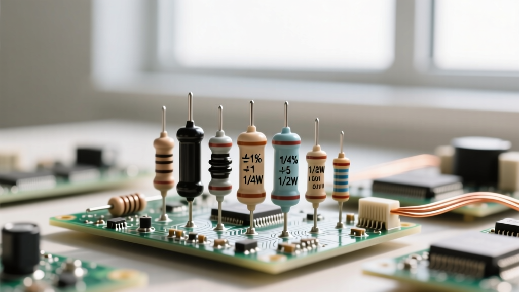
- 1/4W (0.25W): Body size approx. 6.3mm x 2.3mm. The universal standard for breadboarding and general DIY kits (equivalent to MIL-PRF-55182 RN55/RN60 footprints).
- 1/2W (0.5W): Body size approx. 9.0mm x 3.2mm. Used for LED drivers, pull-up networks on higher voltage buses, and snubber circuits.
- 1W and 2W: Often utilize a larger ceramic core and thicker end caps to act as a heatsink. Required for current sensing and power supply bleed networks.
The E-Series Framework: E12, E24, and E96 Explained
Resistors are not manufactured in arbitrary values; they follow the IEC 60063 E-series standard, which spaces values logarithmically to ensure overlap based on the component's tolerance. As detailed in Electronics Tutorials' comprehensive guide to resistor values, understanding these series prevents you from buying kits with useless gaps in your inventory.
Which Series Should You Buy?
For a standard DIY workbench, an E24 series kit with 1% tolerance is the ultimate sweet spot. The E24 series provides 24 values per decade (e.g., 10, 11, 12, 13, 15, 16, 18, 20, 22, 24, 27, 30, 33, 36, 39, 43, 47, 51, 56, 62, 68, 75, 82, 91). While 1% resistors technically belong to the E96 series (96 values per decade), manufacturers produce E24 values in 1% metal film because it streamlines inventory for both precision and general-purpose applications. Avoid E12 kits unless you are strictly doing basic LED limiting or crude pull-ups, as the gaps between values (e.g., jumping from 47 to 56) will frustrate you when designing analog filters or voltage dividers.
Evaluating Standard Resistor Assortment Kits for the Workbench
Buying individual resistors from distributors like DigiKey or Mouser is ideal for production, but for prototyping, a pre-packaged assortment kit is essential. Below is a comparison of the most popular kits available on the market, evaluating their value proposition, organization, and series coverage.
| Brand / Kit | Piece Count | Series & Tolerance | Est. Price | Best Application |
|---|---|---|---|---|
| Bojack 16,000 Piece | 16,000 | E24, 1%, 1/4W | $18 - $22 | High-volume repair shops and university labs. |
| RexQualis 3,000 Piece | 3,000 | E24, 1%, 1/4W | $9 - $11 | Hobbyists and Arduino/Raspberry Pi beginners. |
| Elegoo 1,200 Piece | 1,200 | E24, 1%, 1/4W | $8 - $10 | Compact workbenches with limited drawer space. |
| Joe Knows Electronics | 3,100 | E24, 1%, 1/4W | $25 - $30 | Premium packaging; great for gifting to students. |
When selecting a kit, pay close attention to the packaging. Ziploc bags with poorly printed labels will quickly lead to a chaotic workbench where a 4.7kΩ resistor is indistinguishable from a 47kΩ resistor. Look for kits that come in bound, tear-away booklets or pre-sorted plastic drawer cabinets. As noted in SparkFun's Resistor Tutorial, misreading a color band or grabbing the wrong value from a disorganized bin is one of the most common causes of 'non-functional' prototype circuits.
Parasitics: When 'Standard' Resistors Aren't Standard
If you are designing RF circuits, high-speed digital logic, or precision audio, you must consider the parasitic elements of a standard resistor. A through-hole metal film resistor is not purely resistive; it is a complex impedance network.
- Parasitic Inductance: To achieve specific resistance values, manufacturers cut a helical groove into the metal film layer. This spiral acts as a tiny inductor (typically in the range of 0.1µH to 1µH). At frequencies above 10MHz, this inductance can cause significant impedance spikes.
- Parasitic Capacitance: The ceramic core and the conductive film create a parallel capacitance, usually around 0.1pF to 0.5pF. While negligible at audio frequencies, this capacitance can shunt high-frequency signals to ground in RF applications.
- Voltage Coefficient: In high-voltage applications (e.g., >200V across a single 1/4W resistor), the resistance value can actually shift slightly depending on the applied voltage due to the dielectric properties of the ceramic substrate.
Failure Modes and Troubleshooting Insights
Resistors rarely fail short-circuit. The vast majority of resistor failures result in an open circuit. This occurs when a transient voltage spike or sustained overpowering causes the resistive film to vaporize or melt, breaking the conductive path. In carbon composition resistors, moisture ingress can cause the resistance to drift upwards over time. In metal film resistors, exposure to sulfur-rich environments (common in industrial or automotive settings) can corrode the end caps, leading to intermittent connections. If you are troubleshooting a dead PCB, always measure standard resistors in-circuit with a multimeter; if a resistor reads significantly lower than its color-code value, it is likely being paralleled by a shorted semiconductor elsewhere on the board. If it reads infinite (OL), the resistor has sacrificed itself to protect the rest of the circuit.
Final Workbench Recommendations
For the definitive DIY electronics workbench, purchase a 3,000-piece E24 1% metal film kit in 1/4W. Supplement this with a small, targeted pack of 1W and 2W metal oxide film resistors for power applications, and a dedicated pack of 0.1Ω to 1Ω current-sense resistors. By understanding the thermal limits, parasitic realities, and E-series mathematics of the standard resistor, you transition from simply wiring components together to engineering robust, reliable electronic systems.