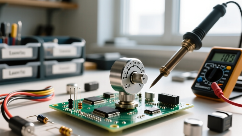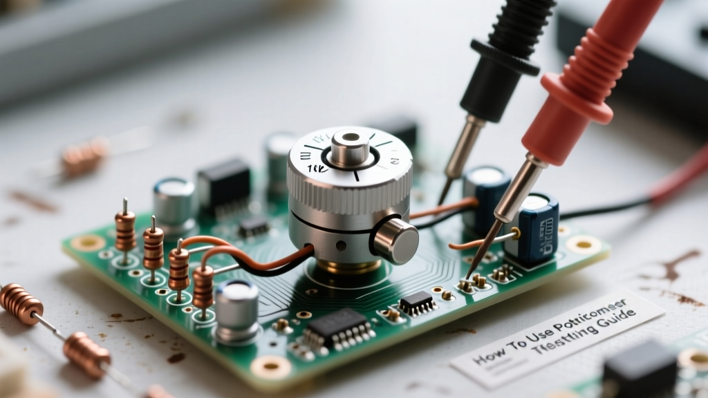

Understanding how to use a potentiometer extends far beyond simply twisting a knob to adjust volume or dim an LED. For electronics engineers, technicians, and advanced DIYers, a potentiometer is a precision electromechanical transducer that requires rigorous testing and measurement to ensure circuit reliability. Whether you are prototyping an analog sensor interface or repairing vintage audio equipment, verifying the electrical characteristics of a potentiometer is critical.
In this comprehensive testing and measurement guide, we will explore the exact methodologies for wiring, measuring, and troubleshooting potentiometers using digital multimeters (DMMs) and oscilloscopes.
The Anatomy of a Potentiometer for Test Engineers
Before applying power or probes, it is essential to understand the physical and electrical topology of the component. A standard rotary potentiometer consists of a resistive track (made of carbon composition, cermet, or conductive plastic) and a movable wiper. Electrically, it presents three terminals:
- Terminal 1 (CCW): The counter-clockwise end of the resistive track. Typically tied to ground in DC circuits.
- Terminal 2 (Wiper): The movable contact that sweeps across the track. This is your output or variable node.
- Terminal 3 (CW): The clockwise end of the resistive track. Typically tied to the reference voltage.
Pro-Tip: When testing unmarked components, never assume terminal 2 is the wiper. Always perform a continuity sweep with a DMM while rotating the shaft to definitively identify the wiper pin.
Configuring and Measuring a Voltage Divider Circuit
The most common application when learning how to use a potentiometer is as a voltage divider. In this configuration, the potentiometer acts as two series resistors whose ratio changes based on the wiper's position.
Wiring and Verification Steps
- Connect Terminal 1 to Ground (0V) and Terminal 3 to your reference voltage (e.g., 5V from a microcontroller or a bench power supply).
- Connect Terminal 2 (Wiper) to the input of your measurement device (DMM or oscilloscope) or an ADC pin.
- Apply power and measure the voltage at the wiper.
According to the fundamental voltage divider rule detailed by Electronics Tutorials, the output voltage is calculated as Vout = Vin × (Rwiper-to-GND / Rtotal). If your 10kΩ potentiometer is set exactly to the mechanical midpoint, a linear taper pot should yield exactly 2.500V (assuming a 5.000V input). Any deviation beyond ±2% indicates a non-linear taper or a degraded resistive track.
Wiring and Testing a Rheostat (Variable Resistor)
When you need to vary current rather than voltage—such as controlling motor speed or adjusting LED brightness—you configure the potentiometer as a rheostat. This requires only two terminals: the wiper and one end terminal.
To test this configuration safely, always wire the unused end terminal directly to the wiper terminal. This prevents an open-circuit condition if the wiper loses contact with the track due to vibration or mechanical wear. Measure the resistance across the wiper and the remaining free terminal using a DMM (like the Fluke 87V) while sweeping the knob. You should observe a smooth, monotonic change from near 0Ω up to the component's rated maximum resistance.
Identifying Potentiometer Taper Using a Digital Multimeter
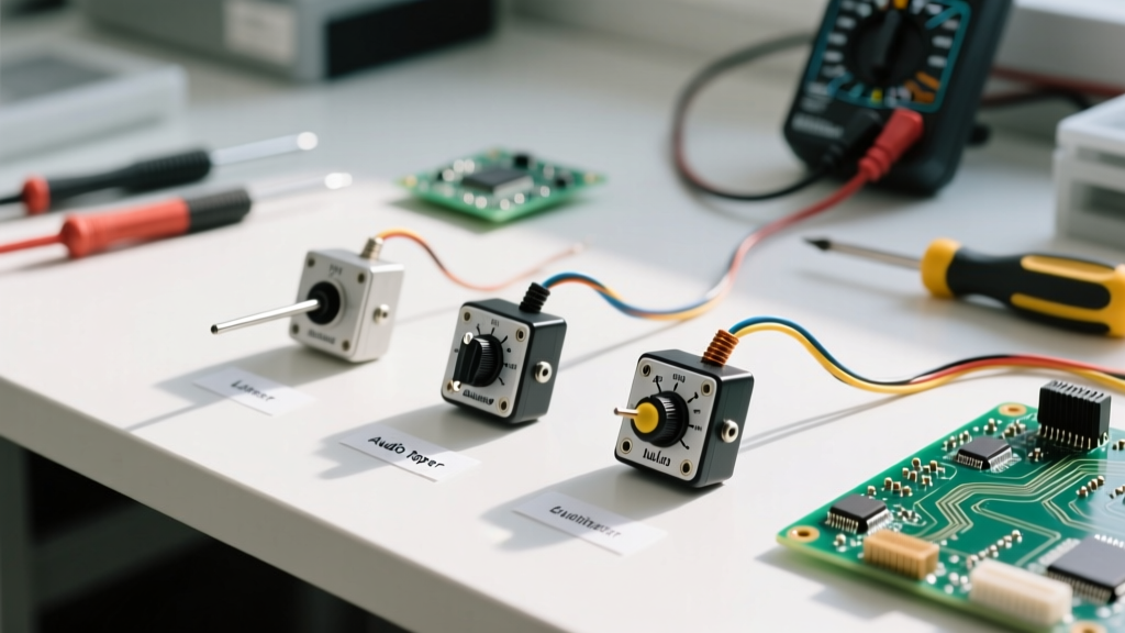
One of the most frequent challenges in the lab is identifying the taper of an unmarked replacement potentiometer. The taper defines the mathematical relationship between the mechanical shaft rotation and the electrical resistance. According to Bourns Application Notes, the three primary tapers are Linear (B-taper), Audio/Logarithmic (A-taper), and Reverse Logarithmic (C-taper).
You can definitively identify an unknown taper using the 50% Rotation Test:
- Measure the total resistance across Terminals 1 and 3 (e.g., 10,000Ω).
- Connect your DMM probes to Terminal 1 (Ground) and Terminal 2 (Wiper).
- Rotate the shaft to exactly 50% of its mechanical travel (using a calibrated dial knob or visual center-mark).
- Record the resistance and compare it to the chart below.
| Taper Type | Marking Code | Resistance at 50% Rotation | Primary Application |
|---|---|---|---|
| Linear | B (e.g., B10K) | 50% of Total (5,000Ω) | Sensor calibration, voltage dividers, function generators |
| Logarithmic (Audio) | A (e.g., A10K) | ~10% to 15% of Total (1,000Ω - 1,500Ω) | Audio volume controls (matches human ear perception) |
| Reverse Logarithmic | C (e.g., C10K) | ~85% to 90% of Total (8,500Ω - 9,000Ω) | Audio balance/fader controls, specific tone circuits |
Advanced Dynamic Testing: Measuring Contact Resistance Variation (CRV)
Static resistance measurements only tell half the story. In high-fidelity audio or precision measurement circuits, the dynamic behavior of the wiper is paramount. Contact Resistance Variation (CRV), also known as track noise or wiper noise, is the transient fluctuation in resistance that occurs while the wiper is in motion.
Oscilloscope Testing Methodology
To measure CRV, you cannot rely on a standard DMM, as its sampling rate is far too slow to catch microsecond-level dropouts. Instead, use an oscilloscope:
- Inject a constant, low-noise DC current (e.g., 10mA) through the potentiometer track using a precision current source.
- Connect the oscilloscope probe (set to AC coupling, high sensitivity in the mV range) to the wiper.
- Rotate the shaft continuously at a steady speed of approximately 20 RPM.
- Observe the waveform. A healthy cermet or conductive plastic pot (like the Vishay P10 series) will show a relatively flat baseline with noise spikes typically below 2mV. A worn carbon composition pot will exhibit massive voltage spikes (often >50mV), indicating physical pitting or oxidation on the track.
This dynamic testing methodology aligns with the IEC 60195 testing standards for evaluating the mechanical and electrical lifespan of variable resistors.
Troubleshooting Common Failure Modes in the Lab
When a circuit fails and the potentiometer is the prime suspect, systematic troubleshooting is required. Here are the most common failure modes and how to measure them:
1. End Resistance (Residual Resistance)
Even when a potentiometer is rotated fully to the CCW or CW stop, the resistance between the wiper and the end terminal will not be absolute zero. This "end resistance" is typically specified between 0.5Ω and 5Ω for standard carbon pots, and < 50mΩ for precision wirewound models. If your DMM reads >20Ω at the mechanical stops, the internal solder joints or wiper spring tension has failed.
2. Dead Spots and Carbon Track Wear
If a DMM reading jumps erratically or drops to infinity (OL) at specific points during rotation, the resistive track has worn away, exposing the non-conductive substrate. In carbon track pots used in guitar pedals or mixers, this is often caused by excessive mechanical cycling. While contact cleaners like DeoxIT D5 can temporarily resolve oxidation-related dead spots, physical track wear mandates component replacement.
3. Moisture and Flux Contamination
In PCB-mounted trimmer potentiometers (like the Bourns 3386P cermet series), leftover soldering flux or environmental humidity can create parallel leakage paths. If you measure a total resistance significantly lower than the rated value (e.g., reading 8.2kΩ on a 10kΩ pot), clean the component thoroughly with 99% isopropyl alcohol and re-test. Moisture ingress is a frequent culprit in outdoor or automotive electronics failures.
Summary
Mastering how to use a potentiometer requires moving beyond basic wiring diagrams and embracing a testing-first mindset. By utilizing DMMs for taper identification, employing oscilloscopes for dynamic CRV analysis, and understanding the physical failure modes of resistive tracks, you can ensure your analog designs remain stable, noise-free, and highly reliable.