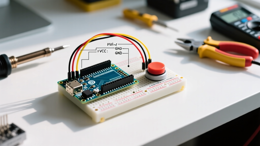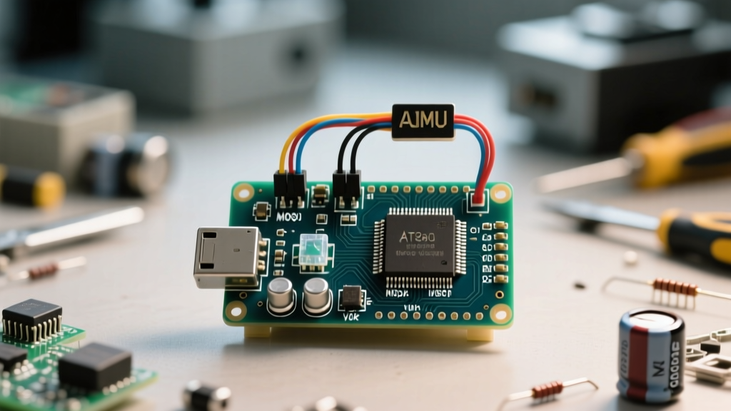

Transitioning from a fully assembled development board to a raw microcontroller is a rite of passage for embedded engineers. This comprehensive arduino guide focuses on deploying the ATmega328P-PU on a breadboard or custom PCB using In-System Programming (ISP). By stripping away the USB-to-Serial overhead and onboard regulators, you reduce unit costs from $25 to under $3 and slash deep-sleep power consumption from milliamps to microamps.
The Economics and Power Matrix: Uno R3 vs. Standalone
Before diving into the wiring, it is crucial to understand why this migration matters for production or battery-operated sensor nodes. The standard Arduino Uno R3 is an excellent prototyping tool, but its ancillary components drain power and inflate the Bill of Materials (BOM).
| Metric | Arduino Uno R3 | Standalone ATmega328P (16MHz) | Standalone (8MHz Internal) |
|---|---|---|---|
| Approx. BOM Cost | $24.00 - $28.00 | $2.85 (DIP-28) | $2.10 (SMD TQFP-32) |
| Active Power (5V) | ~45mA (with LEDs & USB) | ~12mA | ~6mA (at 3.3V) |
| Power Down Sleep | ~15mA (USB chip active) | ~0.1µA | ~0.1µA |
| Footprint | 68.6 x 53.3mm | Custom (e.g., 20x15mm) | Custom (e.g., 10x10mm) |
Hardware BOM: Sourcing the Right Components
To follow this arduino guide successfully, you need more than just the microcontroller. Sourcing the correct oscillator and decoupling capacitors is where most beginners fail, resulting in unstable clock signals and random brownouts.
- MCU: ATmega328P-PU (DIP-28 package for breadboards). Ensure it has the 'P' (picoPower) and 'V' or standard voltage rating. Beware of counterfeit chips from unauthorized AliExpress vendors that ship with corrupted factory fuses.
- Oscillator: 16.000 MHz HC-49S Quartz Crystal. While ceramic resonators (like the ZTT-16.00MT) are cheaper and require no load capacitors, quartz crystals offer superior frequency stability (±20ppm vs ±0.5%) which is critical for UART baud-rate accuracy and RF timing.
- Load Capacitors: Two 22pF ceramic capacitors (C0G/NP0 dielectric preferred) for the crystal.
- Decoupling: 100nF (0.1µF) MLCC capacitors. You need three: one for VCC/GND, one for AVCC/GND, and one for AREF/GND.
- ISP Programmer: A genuine Arduino Nano or a dedicated USBasp. If using a Nano, you must wire a 10µF electrolytic capacitor between its RESET and GND pins to disable its auto-reset circuit during programming.
From Breadboard to PCB: SMD Considerations
While the DIP-28 package is ideal for breadboarding, professional deployments require the TQFP-32 package (ATmega328P-AU). Transitioning to surface-mount design (SMD) introduces new manufacturing variables. When designing your schematic in KiCad or Altium, ensure you include a 10kΩ pull-up resistor on the RESET line to prevent noise-induced brownouts in high-EMI environments. For assembly, use SAC305 lead-free solder paste and a Type RMA (Rosin Mildly Activated) flux. Reflow profiling must adhere to the Microchip moisture sensitivity level (MSL) guidelines to prevent package cracking from trapped moisture.
Wiring the ISP Header and Power Decoupling
The ISP protocol relies on SPI (Serial Peripheral Interface) to communicate with the AVR's internal flash memory. The standard AVR ISP pinout consists of six connections: MISO, VCC, SCK, MOSI, RESET, and GND.
Critical E-E-A-T Warning: Never hot-plug an ISP connection. Always connect GND first, then VCC, and finally the SPI data lines. Hot-plugging can induce ground bounce, potentially latching up the ATmega328P's I/O protection diodes and permanently bricking the silicon.
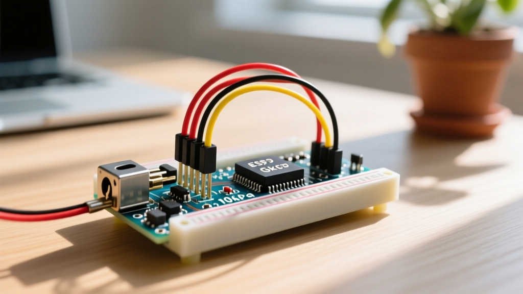
When wiring the crystal oscillator to pins 9 (XTAL1) and 10 (XTAL2), keep the traces or breadboard jumpers as short as physically possible. Parasitic capacitance from long jumper wires can shift the resonant frequency, causing the avrdude software to lose synchronization during the flash verification phase. Furthermore, the 100nF decoupling capacitors must be placed within 2mm of the MCU's VCC (Pin 7) and AVCC (Pin 20) pins. AVCC powers the internal ADC and digital I/O buffers; leaving it un-decoupled will result in erratic analog readings and SPI communication drops.
Choosing Your ISP Programmer: USBasp vs. Arduino as ISP
While using an Arduino Nano as an ISP programmer is a great zero-cost hack, it is not without flaws. The Nano relies on bit-banging SPI via its firmware, which can struggle with timing precision on heavily loaded PCs. For frequent standalone deployments, investing in a dedicated USBasp programmer is highly recommended. A genuine USBasp (or a high-quality clone with the correct ATmega8A/ATmega88 firmware) handles SPI clock division at the hardware level, ensuring reliable communication even with long ribbon cables. Furthermore, USBasp natively supports 3.3V logic levels via an onboard jumper, eliminating the need for external level shifters when programming 3.3V AVR variants or other microcontrollers like the ATmega328V.
Step-by-Step: Burning the Bootloader in IDE 2.x
The Arduino IDE 2.x interface introduced a more robust backend based on arduino-cli, but the ISP workflow remains largely identical to the legacy 1.8.x branch.
- Connect your programmer (e.g., Arduino Nano) to your PC and upload the ArduinoISP sketch (found under File > Examples > 11.ArduinoISP). Remember to install the 10µF capacitor on the programmer's RESET pin after the upload finishes. For official documentation, refer to the Arduino ISP Tutorial.
- Wire the Nano to the target ATmega328P: Nano Pin 10 to Target RESET, Pin 11 to MOSI, Pin 12 to MISO, Pin 13 to SCK, plus 5V and GND.
- In the IDE, navigate to Tools > Board and select Arduino Uno (or ATmega328 on a breadboard (8 MHz internal clock) if you have installed the minimal hardware package via the Boards Manager URL from Nick Gammon's extensive AVR guide).
- Select Tools > Programmer > Arduino as ISP. Do not select 'ArduinoISP' (the latter is for older, deprecated workflows).
- Click Tools > Burn Bootloader. The IDE will compile the Optiboot hex file, set the correct AVR fuse bits (clearing the CKDIV8 fuse to disable the factory 8MHz clock divider), and flash the 512-byte bootloader.
Troubleshooting Matrix: Decoding avrdude Failures
When working with raw silicon, the IDE's error messages can be cryptic. Below is a diagnostic matrix for the most common avrdude failures encountered when following any raw-chip arduino guide.
| avrdude Error Message | Expected Signature | Actual Signature Read | Root Cause & Hardware Fix |
|---|---|---|---|
Yikes! Invalid device signature. | 0x1E 0x95 0x0F | 0x00 0x00 0x00 | No clock signal. Check crystal wiring, or the chip is set to external clock but no crystal is present. Inject an 8MHz square wave on XTAL1 to unbrick. |
Yikes! Invalid device signature. | 0x1E 0x95 0x0F | 0xFF 0xFF 0xFF | VCC or AVCC is missing. The chip is unpowered, or the ISP header VCC pin is not connected to both Pin 7 and Pin 20. |
Yikes! Invalid device signature. | 0x1E 0x95 0x0F | 0x53 0x76 0x6F (Garbage) | MISO and MOSI are swapped. The programmer is reading its own outgoing SPI data. Swap pins 11 and 12. |
stk500_recv(): programmer is not responding | N/A | N/A | The programmer itself is resetting. You forgot the 10µF capacitor on the Nano's RESET pin, causing the IDE to reset the Nano instead of sending ISP commands. |
Advanced: Bypassing the Bootloader for Direct Hex Flashing
While the Optiboot bootloader is fantastic for iterative development via a USB-Serial adapter, it consumes 512 bytes of flash and introduces a ~500ms boot delay. For production devices, bypassing the bootloader is the professional standard.
By using the ISP header, you can write directly to the application flash section. In the Arduino IDE, simply select Sketch > Upload Using Programmer. This command invokes avrdude with the -U flash:w:sketch.hex:i flag, erasing the chip and writing your sketch starting at memory address 0x0000. To support this, you must also change the fuse settings to allocate 0 bytes for the bootloader (setting the BOOTRST fuse to '1' so the MCU boots directly to the reset vector at 0x0000 instead of the bootloader section). For deep-dive fuse calculations, consult the official Microchip ATmega328P Datasheet, specifically Section 28 on Memory Programming.
Mastering standalone AVR deployment transforms you from a hobbyist assembling modules into an embedded systems engineer designing optimized, low-power hardware. Keep your decoupling tight, your clock traces short, and your avrdude logs open.