
The Anatomy of Your DMM: Ports and Protection
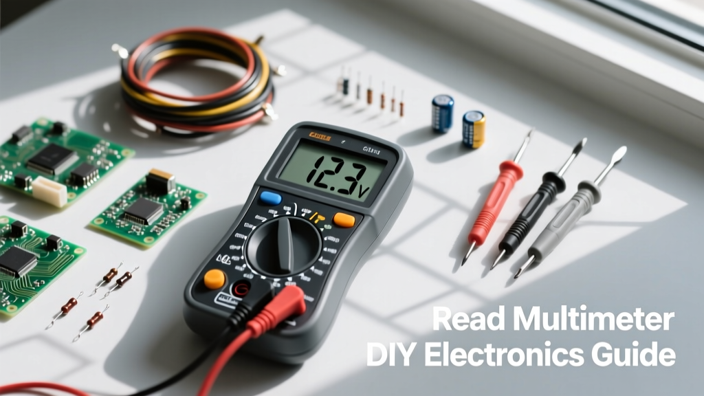
Learning how to read a multimeter begins long before you touch a probe to a circuit. Whether you are using a premium True-RMS Fluke 117 or a budget-friendly AstroAI DM6000AR, the physical interface dictates your safety and accuracy. A Digital Multimeter (DMM) typically features three to four input jacks, and plugging your probes into the wrong ports is the most common way DIYers destroy their equipment.
- COM (Common): The black probe always connects here. It serves as the ground or reference point for all measurements.
- VΩmA (Voltage, Resistance, Milliamps): The red probe connects here for 95% of DIY tasks, including measuring voltage, resistance, continuity, and small currents (usually up to 400mA).
- 10A (High Current): The red probe moves here only when measuring large currents. On many entry-level meters, this port is unfused. If you accidentally leave your red probe in the 10A port and probe a wall outlet, you will create a dead short, resulting in an explosive arc and a destroyed meter.
Always verify your meter's CAT rating before probing mains voltage. A CAT III 600V rating is mandatory for DIY home wiring projects to protect against transient spikes and arc flashes.
Voltage Measurement: Decoding AC, DC, and True-RMS
Voltage is the electrical pressure in a circuit, and understanding how to read a multimeter display for voltage is foundational. You must first determine if you are measuring Direct Current (DC) or Alternating Current (AC).
DC Voltage (V⎓)
Use the DC setting (denoted by a solid line with dashed lines beneath it) for batteries, solar panels, and microcontroller logic like Arduino or Raspberry Pi. When testing a standard 9V alkaline battery, a fresh cell will read around 9.4V to 9.6V. If your display reads 7.8V, the battery is depleted. For automotive 12V systems, a resting battery should read 12.6V; anything below 12.0V indicates a bad cell or deep discharge.
AC Voltage (V~) and True-RMS
Use the AC setting (denoted by a wavy line) for wall outlets and doorbell transformers. Standard US outlets should read between 110V and 125V. However, if you are measuring non-linear loads like dimmer switches or variable frequency drives, a standard "average-responding" meter will give you wildly inaccurate readings. In these cases, you need a True-RMS multimeter to accurately calculate the root mean square of the distorted sine wave. As noted in Fluke's official multimeter guide, True-RMS is essential for modern electronics troubleshooting.
The "OL" vs "0.00" Dilemma
Beginners often panic when their screen displays "OL". In the context of voltage and resistance, "OL" stands for Overload or Out of Limits. It means the value exceeds the meter's current range setting. If you are on a manual-ranging meter, simply bump the dial up to the next highest range. Conversely, a reading of "0.00" means there is absolutely no potential difference between the two probes.
Continuity and Resistance: Tracing the Invisible
Resistance (Ω) measures how much a component opposes electrical flow, while continuity is a simple pass/fail test for whether a complete path exists. Crucial Rule: You must remove all power from the circuit before measuring resistance or continuity. The multimeter injects its own tiny known current to calculate resistance; external voltage will skew the reading and can blow the meter's internal fuse.
According to SparkFun's Multimeter Tutorial, the continuity setting (denoted by a soundwave symbol))) is your best friend for finding broken traces on a PCB or verifying that a switch is actually closing the circuit. When the resistance between the two probes drops below a specific threshold (typically 15Ω to 30Ω, depending on the manufacturer), the meter emits an audible beep. This allows you to keep your eyes on the solder joints rather than staring at the screen.
| Dial Symbol | Measurement Type | Common DIY Application |
|---|---|---|
| V⎓ | DC Voltage | Testing Arduino 5V pins, LiPo batteries, LED strips |
| V~ | AC Voltage | Wall outlets, HVAC control boards, doorbell transformers |
| Ω | Resistance | Verifying resistor color codes, checking heating coils |
| ))) | Continuity | Tracing PCB traces, checking fuses, verifying switch operation |
| -| |- | Capacitance | Testing motor start capacitors (must discharge first!) |
Current Measurement: Avoiding the Blown Fuse Trap
Measuring current (Amps) is where most DIYers make critical errors. Unlike voltage, which is measured in parallel across a component, current must be measured in series. This means you must physically break the circuit and make the multimeter a part of the path so the electrons flow through the meter.
If you are building a custom sensor node and want to know its power draw, you would connect the multimeter between the positive terminal of the battery and the positive rail of your breadboard. If you accidentally connect the probes in parallel across a power source while the dial is set to Amps, you create a short circuit. The meter's internal fuse will blow instantly to save the shunt resistor, and you will be greeted with a blank display or an "OL" error until you open the chassis and replace the ceramic fuse.
Advanced Diagnostics: Diodes and Ghost Voltage
As you progress in DIY electronics, you will encounter scenarios where basic readings don't tell the whole story.
The Diode Test
The diode setting (arrow pointing at a line) measures the forward voltage drop of a semiconductor junction. A standard silicon diode (like the 1N4007) will read between 0.5V and 0.7V. A Schottky diode will read lower, around 0.2V to 0.3V. If you get an "OL" in both directions, the diode is open (blown). If you get 0.00V or a very low reading in both directions, the diode is shorted.
Chasing Ghost Voltage
When working on home wiring or long runs of low-voltage landscape lighting, you might measure 40V to 60V on a wire that should be completely dead. This is "ghost voltage" caused by capacitive coupling from adjacent live wires running in the same conduit. Standard high-impedance digital multimeters (which have an input impedance of 10 Megohms) are sensitive enough to pick up this phantom energy. To eliminate ghost voltage and confirm a wire is truly dead, use a meter with a LoZ (Low Impedance) mode, or parallel a solenoid-style analog tester across the probes to bleed off the capacitive charge.
Practical Maintenance for Reliable Readings
Your multimeter is only as good as its power source and probes. A low battery in the DMM can cause the internal analog-to-digital converter to malfunction, resulting in wildly inaccurate readings that don't trigger the low-battery icon. Furthermore, inspect your probe tips regularly. Oxidized or carbon-scored tips add unwanted resistance to your measurements. Clean them with isopropyl alcohol and a fiberglass scratch pen to ensure your continuity and micro-ohm readings remain precise.