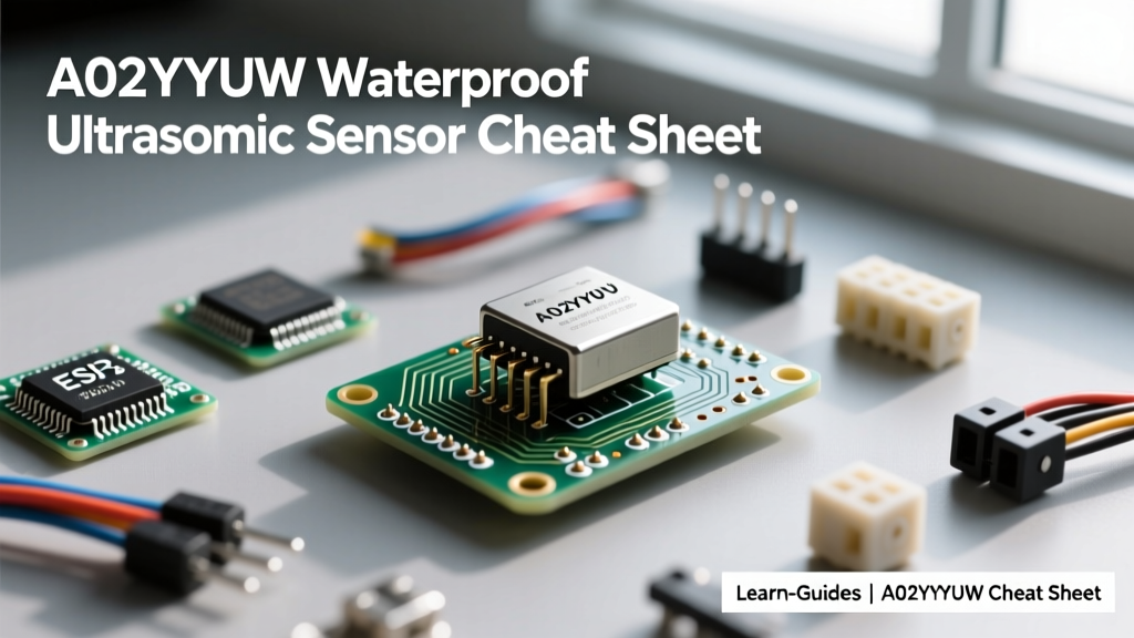

When building outdoor robotics, liquid level monitors, or automotive parking aids, standard open-air ultrasonic sensors quickly fail due to moisture and dust ingress. The A02YYUW waterproof ultrasonic sensor (often manufactured by DYP) solves this with an IP67-rated sealed transducer and a robust UART/I2C digital output. Unlike the popular HC-SR04, which requires precise microsecond timing to read PWM echo pulses, the A02YYUW handles all internal signal processing and simply outputs a clean, serialized distance packet.
This reference guide and cheat sheet provides the exact datasheet specifications, UART protocol decoding, logic-level wiring warnings for 3.3V microcontrollers, and real-world troubleshooting matrices to accelerate your next embedded project.
Quick-Reference Specifications & Pinout Map
Before wiring the sensor to your microcontroller, verify that your power supply can handle the transient current spikes during the acoustic ping cycle. The internal 300kHz closed-type transducer requires a brief surge of power to generate the ultrasonic burst.
| Parameter | Specification | Engineering Notes |
|---|---|---|
| Operating Voltage | 3.3V to 5.5V DC | Tolerant of standard Li-Ion (4.2V) and USB (5V) rails. |
| Peak Current | ~200 mA | Ensure your LDO or buck converter can supply transient spikes. |
| Average Current | ~15 mA | Measured at 10Hz polling rate. |
| Measuring Range | 300 mm to 4500 mm | Objects closer than 300mm fall into the acoustic blind zone. |
| Resolution | 1 mm | Output is strictly in millimeters via UART. |
| Accuracy | ±(1 cm + 1%) | Highly stable at room temperature; degrades slightly in extreme cold. |
| Blind Zone | 0 mm to 300 mm | Do not use for proximity detection under 30cm. |
| Ingress Protection | IP67 | Submersible briefly; ideal for outdoor and high-humidity environments. |
Standard 4-Pin UART Cable Pinout
- Red (VCC): Positive power supply (3.3V - 5.5V).
- Black (GND): Common ground. Must be shared with the microcontroller.
- Green (TX): UART Transmit (Sensor output to MCU RX).
- White (RX): UART Receive (MCU TX to Sensor input, used for I2C/UART mode switching or configuration commands).
UART Communication Protocol Decoded
The A02YYUW defaults to a UART baud rate of 9600 bps, 8 data bits, no parity, 1 stop bit (8N1). The sensor continuously outputs a 4-byte data frame every 100ms (10Hz). Understanding this frame structure is critical for writing a robust parsing algorithm that avoids buffer desynchronization.
The 4-Byte Frame Structure
- Byte 1 (Header): Always
0xFF. Used to synchronize the serial buffer. - Byte 2 (Data_H): High byte of the distance value.
- Byte 3 (Data_L): Low byte of the distance value.
- Byte 4 (Sum): Checksum to verify data integrity.
Checksum Formula:Sum = (0xFF + Data_H + Data_L) & 0x00FF
Distance Calculation:Distance (mm) = (Data_H << 8) | Data_L
Example: If the sensor reads 1200mm (0x04B0), the frame will be: 0xFF (Header), 0x04 (Data_H), 0xB0 (Data_L), 0xC3 (Sum). If your microcontroller receives a frame where the calculated sum does not match Byte 4, discard the packet to prevent ghost readings.
Hardware Comparison Matrix
How does the A02YYUW stack up against other common ultrasonic modules on the market? The table below highlights why DIYers and engineers upgrade from standard modules for harsh environments.
| Feature | DYP A02YYUW | JSN-SR04T (v2.0) | HC-SR04 | MaxBotix MB7389 |
|---|---|---|---|---|
| Interface | UART / I2C | Analog / PWM | PWM (Echo/Trig) | UART / Analog / RS232 |
| Waterproofing | IP67 (Sealed) | IP67 (Sealed) | None (Open mesh) | IP67 (Sealed) |
| Blind Zone | 300 mm | 200 mm | 20 mm | 300 mm |
| Max Range | 4500 mm | 4000 mm | 4000 mm | 5000 mm |
| Avg. Price (USD) | ~$18.00 | ~$6.00 | ~$2.00 | ~$130.00 |
| MCU Timing Load | Low (Async UART) | High (ADC/PWM) | High (uS Pulse) | Low (Async UART) |
While the JSN-SR04T is cheaper, its analog and PWM outputs are highly susceptible to electromagnetic interference (EMI) over long cable runs. The A02YYUW's digital UART output allows for reliable data transmission over several meters of shielded cable without signal degradation.
ESP32 & Arduino Wiring (Logic Level Warnings)
The most common point of failure when integrating the A02YYUW with modern 3.3V microcontrollers like the ESP32 or Raspberry Pi Pico is UART logic level mismatch. According to the ESP32 GPIO reference guide, the pins are strictly 3.3V tolerant.
The 5V Power Trap
The A02YYUW operates from 3.3V to 5.5V. However, the sensor's TX pin outputs a logic HIGH voltage that matches its VCC supply. If you power the sensor with 5V, its TX pin will output 5V. Feeding a 5V UART signal directly into an ESP32 RX pin will permanently damage the microcontroller's GPIO circuitry.
Safe Wiring Configurations
- Configuration A (3.3V System): Power the A02YYUW directly from the ESP32's 3.3V pin. The sensor will draw up to 200mA during the ping. Ensure your ESP32 dev board's onboard LDO can handle this transient load without browning out. If so, connect TX directly to the ESP32 RX pin.
- Configuration B (5V System with Voltage Divider): Power the sensor from a 5V rail (recommended for high-current stability). Place a voltage divider (e.g., 1kΩ and 2kΩ resistors) on the sensor's TX line before it enters the ESP32's RX pin to step the 5V logic down to a safe ~3.3V.
For the RX pin on the sensor (White wire), you can generally leave it disconnected if you are only reading continuous UART data, as the sensor defaults to automatic serial output on boot.
Real-World Failure Modes & Troubleshooting
Even with an IP67 rating, environmental physics and software bugs can cause erratic behavior. Use this matrix to diagnose issues in the field.
| Symptom | Root Cause | Engineering Fix |
|---|---|---|
| Readings stuck at 300mm | Target is inside the acoustic blind zone. | Relocate sensor to ensure minimum 350mm clearance to the target surface. |
| Random 4500mm spikes | Acoustic absorption or specular reflection. | Soft materials (foam, fabric) absorb 300kHz waves. Angled surfaces deflect them. Ensure target is hard and perpendicular. |
| UART Checksum Errors | EMI on the serial line or baud rate drift. | Use shielded twisted-pair cable for runs over 1 meter. Verify MCU crystal oscillator accuracy. |
| Sensor overheats / resets | Voltage sag during 200mA ping spike. | Add a 100µF to 470µF decoupling capacitor across the VCC and GND pins at the sensor head. |
| Condensation errors | Seal compromised, moisture on transducer. | Apply a thin layer of hydrophobic nano-coating to the exterior mesh; replace if internal fogging occurs. |
C++ Implementation Snippet for ESP32
Below is a robust, non-blocking C++ snippet utilizing HardwareSerial on an ESP32. This code implements a state machine to parse the 4-byte UART frame, verify the checksum, and prevent buffer desynchronization. For more on serial handling, refer to the Arduino SoftwareSerial documentation.
#include <HardwareSerial.h>

HardwareSerial ultrasonicSerial(2); // Use UART2 on ESP32

const int RX_PIN = 16;
const int TX_PIN = 17; // Optional, can be left unconnected

void setup() {
  Serial.begin(115200);
  ultrasonicSerial.begin(9600, SERIAL_8N1, RX_PIN, TX_PIN);
  Serial.println("A02YYUW Sensor Initialized...");
}

void loop() {
  if (ultrasonicSerial.available() >= 4) {
    uint8_t header = ultrasonicSerial.read();
    if (header == 0xFF) {
      uint8_t dataH = ultrasonicSerial.read();
      uint8_t dataL = ultrasonicSerial.read();
      uint8_t sum = ultrasonicSerial.read();

      // Verify Checksum
      if (sum == ((0xFF + dataH + dataL) & 0x00FF)) {
        uint16_t distance_mm = (dataH << 8) | dataL;
        Serial.print("Valid Distance: ");
        Serial.print(distance_mm);
        Serial.println(" mm");
      } else {
        Serial.println("Checksum Error - Packet Discarded");
      }
    } else {
      // Buffer desync: flush remaining bytes to re-align with next 0xFF header
      while(ultrasonicSerial.available() > 0) { ultrasonicSerial.read(); }
    }
  }
}
By treating the A02YYUW not just as a simple component, but as a serialized data node, you can build highly reliable, weather-proof distance measurement systems that survive where standard hobbyist sensors fail. Always prioritize power decoupling and logic-level protection to ensure long-term deployment stability.