
Beyond the Cheat Sheet: A Workflow-Centric Approach
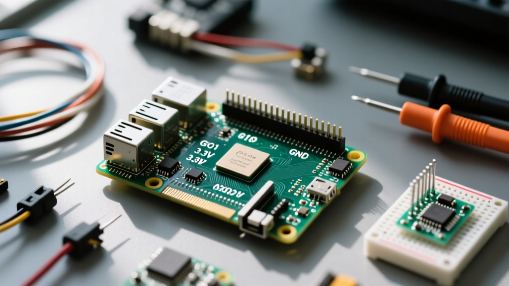
When embedded engineers and makers first look at the raspi 4 gpio pinout, they usually see a simple map of 40 physical pins. However, treating this 40-pin header merely as a static reference chart is a primary cause of delayed prototyping, fried SoCs, and mysterious boot failures. To truly optimize your hardware workflow, you must shift your perspective from memorizing pin numbers to understanding the electrical and logical constraints of the BCM2711 chip that drives them.
In this guide, we will bypass the basic pin diagrams and focus on workflow optimization: how to safely map peripherals, avoid boot-sequence conflicts, manage 3.3V logic translation, and implement software-driven pin verification before you ever connect a wire.
The 3.3V Logic Reality Check (And How Not to Fry Your BCM2711)
The most common workflow bottleneck for makers transitioning from 5V Arduino environments to the Raspberry Pi 4 is logic level mismatch. The BCM2711 SoC operates strictly at 3.3V logic. Applying 5V to any GPIO pin will instantly destroy the pin's internal clamping diodes and likely kill the entire SoC.
To optimize your component sourcing workflow, adopt a '3.3V First' procurement strategy. Standardize on 3.3V native sensors like the BME280 (environmental), VL53L0X (Time-of-Flight), and ADS1115 (ADC). When 5V peripherals are unavoidable, do not rely on simple resistor voltage dividers for high-speed or bidirectional communication; they introduce capacitance that degrades signal integrity above 100kHz.
Optimizing Logic Level Translation
- For I2C (Open-Drain): Use N-channel MOSFET-based shifters like the BSS138 or dedicated ICs like the NXP PCA9306. These handle bidirectional data without the bus contention issues found in push-pull shifters.
- For SPI and High-Speed GPIO: Utilize auto-directional translators like the Texas Instruments TXB0108 or TXS0108E. Be aware that the TXB0108 has weak drive strength and struggles with long wires or high-capacitance loads, whereas the TXS0108E handles open-drain and push-pull but requires careful pull-up resistor management.
Mapping the Minefield: Boot-Critical Pins to Avoid
A major disruption in any prototyping workflow is a Raspberry Pi that refuses to boot after wiring a new sensor harness. The BCM2711 samples specific GPIO states during the early bootloader phase to determine boot modes and peripheral initialization. If your external circuitry pulls these pins to an unexpected state, the Pi will hang indefinitely.
Workflow Rule of Thumb: Never connect external circuits with strong pull-down or pull-up resistors to GPIO 0, 1, 2, 3, 14, or 15 unless you fully understand the boot sequence implications. Always use a multimeter to verify the resting state of these pins on your custom PCB before applying power to the Pi.
GPIO Pin Risk Matrix for Prototyping
| GPIO BCM | Physical Pin | Default Function | Workflow Risk Level | Specific Failure Mode |
|---|---|---|---|---|
| 0, 1 | 27, 28 | I2C0 (ID EEPROM) | High | Used for HAT identification at boot. External I2C devices can cause boot hangs or incorrect device tree overlays. |
| 2, 3 | 3, 5 | I2C1 (Main Bus) | Medium | Features hardware 1.8kΩ pull-ups to 3.3V. Safe for most I2C, but adding external pull-ups can cause bus capacitance issues. |
| 14, 15 | 8, 10 | UART0 (TX/RX) | Critical | Acts as the serial console. If GPIO 15 (RX) is pulled low during boot, the bootloader halts waiting for serial input. |
| 4 to 13 | 7, 11, 12, etc. | General Purpose | Safe | Standard GPIO. Default to inputs with no pull-ups/downs. Ideal for initial sensor prototyping. |
For a comprehensive visual reference during your design phase, keeping a bookmark to Pinout.xyz is an essential workflow habit, as it details the alternate functions (ALT0-ALT5) for every BCM pin.
Software-Driven Pinout Management and Verification
Relying on physical multimeter probing for every pin state is inefficient. Optimize your debugging workflow by integrating software-based pin verification directly into your deployment pipeline.
The 'pinout' CLI Tool
The Raspberry Pi OS includes the gpiozero Python library, which features a built-in command-line tool. By simply typing pinout in the terminal, you get an ASCII-art representation of the raspi 4 gpio pinout tailored to your specific board revision. This is invaluable when SSH-ing into a headless Pi mounted inside an enclosure.
Live State Debugging with raspi-gpio
When a sensor isn't responding, you need to know if the pin is configured correctly by the kernel. The raspi-gpio tool allows you to inspect and manipulate pin states at the register level without writing a Python script.
# Check the current state, pull, and function of GPIO 17
raspi-gpio get 17

# Force GPIO 17 to an output and drive it high for hardware testing
raspi-gpio set 17 op dh
Integrating a pre-flight bash script that runs raspi-gpio get on all expected pins before launching your main application can save hours of debugging hardware that was accidentally left in an alternate SPI or UART mode by a rogue device tree overlay.
Power Delivery: The 5V and GND Bottleneck
While the data pins require careful logic management, the power pins dictate the physical limits of your project. The raspi 4 gpio pinout provides 5V on Pins 2 and 4, and multiple Ground connections. However, the 5V pins are directly tied to the USB-C power input rail.
A critical workflow optimization is establishing a strict rule against backpowering the Pi via the 5V GPIO pins. The Raspberry Pi 4 features a sophisticated USB-C Power Delivery (PD) negotiation circuit and a polyfuse for overcurrent protection. If you inject 5V directly into the GPIO header from an external bench supply or battery pack, you bypass these protection circuits. This can lead to ground loops, damaged USB-C controllers, and unstable voltage regulation under load.
For high-current peripherals (like LED matrices or servo motors), always use a separate 5V power supply, tying only the Ground (GND) to the Pi's GPIO GND pins (e.g., Pin 6, 9, 14, 20, 25, 30, 34, 39) to establish a common reference voltage. According to the official Raspberry Pi configuration documentation, the total current draw from all 3.3V GPIO pins combined should not exceed 50mA, and individual pins should be limited to 16mA.
Physical Prototyping Workflows: Moving Beyond Dupont Wires
The final stage of workflow optimization involves physical reliability. Messy breadboards and loose Dupont jumper wires are the enemy of stable I2C and SPI communication, which are highly susceptible to capacitance and crosstalk.
- Phase 1 (Proof of Concept): Use a high-quality solderless breadboard with short, pre-cut jumper wires. Keep I2C and SPI traces under 10cm.
- Phase 2 (Integration): Transition to a Terminal Block HAT or a custom perfboard. Soldering headers and using screw terminals eliminates intermittent contact failures that mimic software bugs.
- Phase 3 (Deployment): Design a custom PCB or use Flexible Flat Cables (FFC) to connect the Pi to remote sensor nodes, ensuring proper shielding for high-speed clock lines.
Summary Checklist for Your Next Build
Before powering on your next Raspberry Pi 4 project, run through this optimized pre-flight checklist:
- Verify all external sensors are 3.3V tolerant or properly level-shifted.
- Ensure GPIO 14 and 15 are not pulled low by external UART circuitry.
- Confirm that
config.txtoverlays match your physical wiring (e.g.,dtparam=i2c_arm=on). - Check that high-current loads are powered externally with a shared GND.
- Run
raspi-gpio getto verify kernel pin states before executing application code.
By treating the raspi 4 gpio pinout not just as a map, but as a set of electrical and logical rules, you transform your prototyping process from a game of trial-and-error into a predictable, professional engineering workflow. For deeper software integration, refer to the gpiozero documentation to master Python-based hardware abstraction.