
Why Add an OLED to Your Headless Raspberry Pi?
Running a Raspberry Pi in 'headless' mode (without a monitor) is the standard for everything from Home Assistant servers to Pi-hole DNS sinks. However, there are countless scenarios where you need immediate, localized visual feedback without SSH-ing into the device or pulling out an HDMI cable. This is exactly where a Raspberry Pi OLED display becomes an indispensable hardware addition.
Whether you are building a portable retro-gaming console, a 3D printer controller running OctoPrint, or a network-attached storage (NAS) dashboard, a tiny 0.96-inch or 1.3-inch OLED provides critical telemetry. It can display CPU temperature, current IP addresses, memory usage, or custom boot animations. In this comprehensive project tutorial, we will cover the physical wiring, the software configuration, and the Python scripting required to get an I2C OLED display running reliably on any Raspberry Pi model, from the Pi Zero 2 W to the Raspberry Pi 5.
Hardware Selection: The SSD1306 vs. The Clone Problem
Before writing a single line of code, you must understand the hardware landscape of cheap I2C OLED modules. The vast majority of tutorials assume you are using an SSD1306 controller. However, the market is flooded with visually identical modules that use the SH1106 or SSD1327 controllers. Using the wrong Python library for your specific silicon will result in a frustrating black screen.
| Controller IC | Typical Resolution | Default I2C Address | Common Real-World Issue |
|---|---|---|---|
| SSD1306 | 128x64 (0.96') | 0x3C or 0x3D | Industry standard; widely supported by all libraries. |
| SH1106 | 132x64 (1.3') | 0x3C | Often mislabeled as SSD1306 by sellers. Requires a 2-pixel X-axis offset in code. |
| SSD1327 | 128x128 (1.5') | 0x3C | Supports 16-level grayscale. Will crash standard monochrome libraries. |
Pro-Tip for Purchasers: If you buy a 1.3-inch OLED from Amazon or AliExpress, it is almost certainly an SH1106, even if the product title explicitly says 'SSD1306'. Always verify your controller using the I2C detect tool or check the silkscreen on the back of the PCB before writing your Python script.
Understanding I2C Bus Capacitance and Pull-Up Resistors
The Raspberry Pi's primary I2C bus (I2C1) operates at 3.3V logic levels. The official Raspberry Pi schematic includes 1.8kΩ pull-up resistors on GPIO 2 (SDA) and GPIO 3 (SCL) tied to the 3.3V rail. Most cheap OLED breakout boards also include their own 10kΩ pull-up resistors. When you connect the display, these resistors act in parallel, lowering the total pull-up resistance. While this usually works fine for short wires, if you use long jumper cables or daisy-chain multiple I2C sensors, the bus capacitance increases, leading to signal degradation and random I2C timeouts.
Physical Wiring: Pi GPIO to OLED Pinout
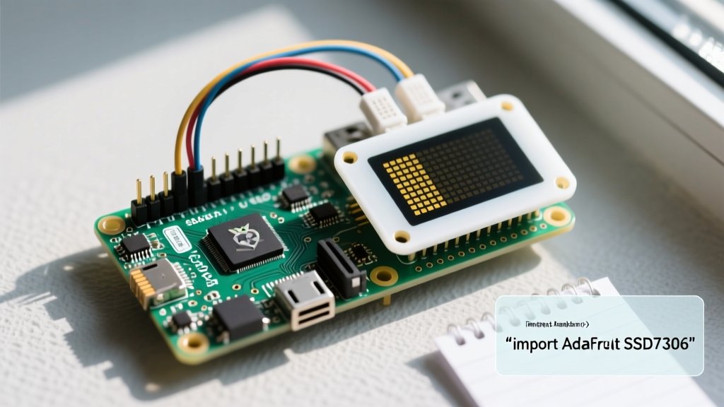
Wiring an I2C Raspberry Pi OLED display is remarkably straightforward because it only requires four connections. You will need a set of female-to-female Dupont jumper wires. Here is the exact pinout mapping for all Raspberry Pi models featuring the 40-pin header:
- VCC (OLED) ➔ Pin 1 (3.3V Power) on the Pi. Never connect this to 5V (Pin 2) unless your specific OLED breakout board has an onboard 5V-to-3.3V voltage regulator. Most raw OLED panels will permanently burn out at 5V.
- GND (OLED) ➔ Pin 6 (Ground) on the Pi.
- SCL (OLED) ➔ Pin 5 (GPIO 3 / I2C1 SCL) on the Pi.
- SDA (OLED) ➔ Pin 3 (GPIO 2 / I2C1 SDA) on the Pi.
Hardware Warning: The Flexible Printed Circuit (FPC) ribbon connecting the glass OLED panel to the PCB is notoriously fragile on budget modules. Do not bend this ribbon at a sharp 90-degree angle during enclosure mounting, as the microscopic copper traces will snap, resulting in dead pixel columns.
Enabling I2C and Installing Python Libraries
By default, the I2C interface is disabled on Raspberry Pi OS to save system resources. You must enable it via the terminal.
Step 1: Enable the I2C Interface
Open your terminal and run the Raspberry Pi configuration tool:
sudo raspi-configNavigate to Interface Options > I2C and select Yes to enable it. Reboot your Pi with sudo reboot to apply the changes. For more details on Pi interfaces, refer to the official Raspberry Pi I2C documentation.
Step 2: Verify the Hardware Connection
Install the I2C tools package and scan the bus to ensure your Pi sees the OLED display:
sudo apt update
sudo apt install i2c-tools
i2cdetect -y 1
You should see a grid output. If your display is detected, you will see 3c (or occasionally 3d) in the grid. If the grid is completely empty, check your wiring and ensure VCC is receiving a stable 3.3V.
Step 3: Install the Luma.OLED Python Library
While Adafruit's CircuitPython libraries are popular, the luma.oled library is a native, highly optimized Python alternative that excels on standard Raspberry Pi OS environments. It supports Pillow (PIL) for advanced drawing and text rendering.
sudo pip3 install luma.oled PillowWriting the Python Display Script
Now we will write a Python script to initialize the display and render text. Create a new file named oled_status.py and paste the following code:
import time
import os
from luma.core.interface.serial import i2c
from luma.core.render import canvas
from luma.oled.device import ssd1306, sh1106
from PIL import ImageFont, ImageDraw

# Initialize the I2C interface
serial = i2c(port=1, address=0x3C)

# Initialize the device (Change to sh1106(serial) if using a 1.3' clone)
device = ssd1306(serial, rotate=0)

# Load a custom font (Ensure this path exists on your Pi OS)
try:
    font = ImageFont.truetype('/usr/share/fonts/truetype/dejavu/DejaVuSans-Bold.ttf', 14)
    font_small = ImageFont.truetype('/usr/share/fonts/truetype/dejavu/DejaVuSans.ttf', 10)
except IOError:
    print('Custom font not found. Falling back to default.')
    font = ImageFont.load_default()
    font_small = font

def get_cpu_temp():
    temp = os.popen('vcgencmd measure_temp').readline()
    return temp.replace('temp=', '').replace("'C\n", '')

def get_ip_address():
    cmd = "hostname -I | awk '{print $1}'"
    return os.popen(cmd).read().strip()

print('Starting OLED Display Loop...')

try:
    while True:
        with canvas(device) as draw:
            # Draw Header
            draw.text((0, 0), 'ElectricalFlux', font=font, fill='white')
            draw.line([(0, 16), (128, 16)], fill='white')

            # Draw System Stats
            draw.text((0, 20), f'IP: {get_ip_address()}', font=font_small, fill='white')
            draw.text((0, 35), f'CPU: {get_cpu_temp()} C', font=font_small, fill='white')
            draw.text((0, 50), 'Status: ONLINE', font=font_small, fill='white')

        time.sleep(2)

except KeyboardInterrupt:
    print('Exiting script.')
    device.cleanup()
Run the script using python3 oled_status.py. Your OLED should immediately illuminate with your Pi's local IP address and live CPU temperature.
Real-World Troubleshooting: Black Screens and I2C Errors
Working with I2C displays in real-world DIY projects rarely goes perfectly the first time. Here are the most common failure modes and how to fix them.
1. The 'Remote I/O Error' Crash
If your Python script crashes with OSError: [Errno 121] Remote I/O error, the Pi lost communication with the OLED mid-transmission. This is almost always caused by voltage ripple on the 3.3V rail or loose Dupont connectors. Soldering header pins directly to the OLED PCB instead of using friction-fit jumper wires eliminates 90% of these errors in permanent installations.
2. The SH1106 Offset Glitch
If your text renders, but the left side of the screen is cut off and wrapped to the right side, you have an SH1106 display disguised as an SSD1306. To fix this, simply change device = ssd1306(serial) to device = sh1106(serial) in the Python script provided above. The luma.oled library handles the 2-pixel RAM offset automatically when the correct hardware class is invoked.
3. OLED Burn-In and Pixel Degradation
OLEDs suffer from burn-in if static elements are left on screen for weeks at a time. If your Pi is acting as a 24/7 server dashboard, implement a software screen-saver. You can do this by shifting the X/Y coordinates of your text by a few pixels every hour, or by blanking the display entirely during nighttime hours using a simple cron job or an ambient light sensor tied to a GPIO interrupt.
For further reading on integrating displays with microcontrollers and SBCs, the Adafruit SSD1306 Guide offers excellent supplementary wiring diagrams. Mastering the Raspberry Pi OLED display transforms a blind, headless server into an interactive, professional-grade piece of hardware.