
The Strategic Role of Raspberry Pi GPIO4 in Home Automation
When building a DIY smart home ecosystem, environmental monitoring is the backbone of automated HVAC control, server rack thermal management, and greenhouse automation. At the heart of many of these Raspberry Pi-based setups is a single, unassuming pin: Raspberry Pi GPIO4. While the Pi offers dozens of general-purpose input/output pins, GPIO4 holds a special architectural significance. It is the hardware default for the 1-Wire interface on Broadcom BCM2835, BCM2711, and BCM2712 chips.
In the context of smart home integration, GPIO4 is almost exclusively utilized to interface with Dallas/Maxim (now Analog Devices) DS18B20 digital temperature sensors. Unlike analog thermistors that require ADCs and suffer from voltage drop over long wires, the DS18B20 outputs a calibrated digital signal. By leveraging Raspberry Pi GPIO4, home lab engineers can daisy-chain multiple sensors on a single data line, pushing precise thermal data directly into platforms like Home Assistant, Node-RED, or openHAB via MQTT.
Physical vs. BCM: Navigating the Pin 7 / BCM 4 Dilemma
One of the most frequent points of failure for beginners integrating Raspberry Pi GPIO4 into smart home dashboards is confusing the physical header pin number with the Broadcom (BCM) GPIO numbering scheme. When configuring software overlays or writing Python scripts using the RPi.GPIO or gpiozero libraries, you must use the BCM designation.
| Function | BCM GPIO | Physical Pin (Header) | Recommended Wire Color |
|---|---|---|---|
| 3.3V Power Rail | N/A | Pin 1 | Orange |
| 1-Wire Data Bus | GPIO4 | Pin 7 | Yellow |
| Ground Reference | N/A | Pin 9 | Black |
Expert Note: Always double-check your pinout with a multimeter before applying power. Physical Pin 7 (GPIO4) sits directly adjacent to Pin 5 (SCL1). Accidentally bridging 3.3V to an I2C clock line can cause unpredictable bus lockups across your entire smart home sensor network.
Wiring the DS18B20: Parasitic vs. External Power Topologies
The DS18B20 supports two power modes: Parasitic Power and External Power. In Parasitic Power mode, the sensor harvests power directly from the data line (GPIO4) during high states, requiring only two wires (Data and Ground). While this saves copper, it is highly discouraged for Raspberry Pi smart home deployments.
The Raspberry Pi's 3.3V rail and GPIO current limits are not optimized to supply the sudden 1.5mA active current spikes required by multiple 1-Wire devices during temperature conversions. Relying on parasitic power via GPIO4 often results in bus brownouts, causing Home Assistant to log 'unavailable' states. For robust smart home integration, always use External Power Mode: connect Pin 1 (VDD) of the sensor to the Pi's 3.3V rail (Physical Pin 1), Pin 2 (DQ) to GPIO4 (Physical Pin 7), and Pin 3 (GND) to Ground (Physical Pin 9).
The 4.7kΩ Pull-Up Resistor: Why Your Smart Home Drops Offline
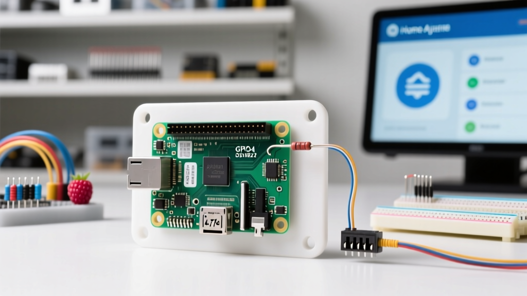
The 1-Wire protocol utilizes an open-drain architecture. This means the DS18B20 can pull the data line low to ground, but it cannot actively drive it high. The line must be pulled high to 3.3V by a resistor. If you omit the 4.7kΩ pull-up resistor between the 3.3V rail and GPIO4, the data line will float, resulting in phantom readings or complete bus failure.
For every 5 meters of cable added to your 1-Wire bus in a smart home environment, the capacitance of the wire increases. If you are running long wires to an attic or crawlspace, you may need to drop the pull-up resistor value to 3.3kΩ or 2.2kΩ to ensure the signal rise time remains within the strict microsecond timing windows required by the 1-Wire protocol.
You can verify the presence of the pull-up on Raspberry Pi GPIO4 using an oscilloscope or a logic analyzer. A healthy 1-Wire bus will show sharp, clean square waves. A floating bus (missing resistor) will show slow, sloping RC charge curves that the Pi's UART/1-Wire controller will misinterpret as data corruption.
Software Configuration: Enabling 1-Wire on Raspberry Pi OS
To activate Raspberry Pi GPIO4 as a 1-Wire master, you must load the appropriate device tree overlay at boot. A critical E-E-A-T detail that plagues modern smart home builders is the shift in directory structures introduced in Raspberry Pi OS 'Bookworm'.
In older OS versions (Bullseye and earlier), the configuration file was located at /boot/config.txt. In Bookworm and newer, the boot partition is mounted differently. You must edit the file located at /boot/firmware/config.txt. Add the following line to the bottom of the file:
dtoverlay=w1-gpio,gpiopin=4,pullup=on
While the pullup=on parameter activates the Pi's internal 50kΩ pull-up resistor, this is generally too weak for reliable smart home operation. It is always best practice to disable the internal pull-up (pullup=off) and rely on your physical external 4.7kΩ resistor for signal integrity. After rebooting, you can verify the kernel has bound the driver by checking lsmod | grep w1 and listing the devices in /sys/bus/w1/devices/.
Home Assistant Integration: Pushing GPIO4 Data via MQTT
While you can read the 1-Wire data locally, a true smart home setup requires pushing this telemetry to a central hub. The most resilient method is using an MQTT broker (like Mosquitto) to bridge the Raspberry Pi and Home Assistant. Instead of relying on brittle local integrations, write a lightweight Python daemon using the paho-mqtt library to parse the sensor data and publish it.
The raw data from GPIO4 is exposed in a file typically named /sys/bus/w1/devices/28-XXXXXXXX/w1_slave. A robust Python script will read this file, verify the CRC checksum on the first line (looking for YES), and extract the integer following t= on the second line. Dividing this integer by 1000 yields the Celsius temperature.
Publish this payload to a topic like homeassistant/sensor/hvac_supply_temp/state. By utilizing the Home Assistant MQTT Sensor integration, you can map this topic directly to a dashboard entity, complete with state classes for long-term statistics tracking in HA's energy and environmental dashboards.
Troubleshooting Table: GPIO4 1-Wire Failure Modes
When integrating Raspberry Pi GPIO4 into mission-critical smart home routines (like preventing pipes from freezing), understanding failure modes is essential. Refer to this diagnostic matrix when your sensors misbehave:
| Symptom in Home Assistant | Root Cause Analysis | Engineering Fix |
|---|---|---|
| Constant 85.0°C Reading | The Pi read the sensor's power-on default register before the 750ms temperature conversion completed. | Implement a strict 750ms delay in your Python script after sending the convert command, or ensure external VDD power is stable. |
| Constant -127.0°C or Disconnected | Missing pull-up resistor, broken data wire, or GPIO4 is being held low by another peripheral. | Verify the 4.7kΩ resistor with a multimeter. Ensure no other HATs are conflicting with Physical Pin 7. |
| Intermittent 'Unavailable' States | Electromagnetic Interference (EMI) from nearby 120V/240V AC lines or inductive loads (like HVAC relays). | Switch to shielded CAT5e cabling. Add a 100nF ceramic bypass capacitor directly across the VDD and GND pins at the sensor. |
Advanced Smart Home Topologies: Long Wire Runs and Noise
The Analog Devices DS18B20 datasheet suggests 1-Wire can run up to 100 meters. However, in a real-world smart home environment filled with Wi-Fi routers, switching power supplies, and AC mains, the practical limit for a passive pull-up on Raspberry Pi GPIO4 is about 10 to 15 meters.
If your smart home requires monitoring a detached garage or a deep well pump house, you must upgrade your bus topology. Use CAT5e Ethernet cable. Dedicate one twisted pair for VDD and GND, and a separate twisted pair for the Data line and a secondary Ground reference. This minimizes the loop area and rejects common-mode noise.
For runs exceeding 20 meters, abandon the passive 4.7kΩ resistor entirely. Instead, use an active 1-Wire master IC like the DS2480B, connected to the Pi via I2C or USB. This chip actively drives the data line high and low, completely eliminating the RC rise-time limitations of a passive pull-up on GPIO4 and ensuring your Home Assistant automations never fail due to a dropped packet.
For deeper insights into configuring device tree overlays and managing hardware pins on the Pi, consult the official Raspberry Pi Configuration Documentation. Mastering Raspberry Pi GPIO4 transforms the Pi from a simple hobby computer into an industrial-grade environmental gateway for your smart home.