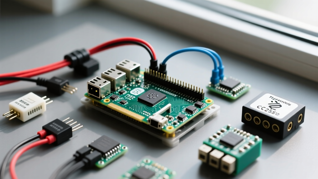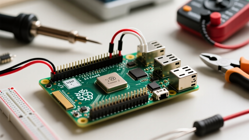

The release of the Raspberry Pi 5 brought massive CPU and I/O upgrades, but for hardware hackers and smart home integrators, the real story lies in the 40-pin GPIO header. While the physical footprint of the raspberry pi 5 pins remains identical to the Pi 4, the underlying architecture has fundamentally changed. Understanding these changes is critical to avoid damaging your board and to ensure your peripherals communicate reliably.
This setup and configuration guide dives deep into the RP1 southbridge architecture, Debian Bookworm configuration quirks, power budget limitations, and essential protection circuits for your next Pi 5 project.
The RP1 Architecture Shift: What Changed Under the Hood?
On previous models, the main Broadcom SoC (like the BCM2711) handled GPIO, USB, and Ethernet directly. The Raspberry Pi 5 delegates these duties to the RP1, a custom-designed southbridge chip built by Raspberry Pi. The main BCM2712 SoC now communicates with the RP1 via a PCIe Gen 2 link.
Why does this matter for your wiring and setup? Because the RP1 handles the actual pin multiplexing, the device tree overlays and pin mappings have shifted. While the primary I2C, SPI, and UART pins remain in their traditional physical locations on the 40-pin header, secondary functions and hardware PWM mappings require updated overlays in the new OS environment.
Power Budgets and Pin Limits: Sizing Your PSU
The Raspberry Pi 5 requires a 5V/5A USB-C Power Delivery (PD) power supply to unlock its full potential. This directly impacts the power budget available on the GPIO header. If you use a standard 5V/3A charger, the board limits the peripheral current budget to protect the system.
Calculating Your 3.3V and 5V Headroom
Before wiring up relays, LED matrices, or sensor arrays, you must understand the current limits of the rails. Exceeding these limits will trigger thermal shutdowns or permanently damage the RP1's internal voltage regulators.
| Rail | Pin Numbers | Voltage | Max Per Pin | Total Rail Budget |
|---|---|---|---|---|
| 5V Power | 2, 4 | 5.0V | 3.0A (Combined) | Depends on PSU (Up to 5A total system) |
| 3.3V Power | 1, 17 | 3.3V | 50mA | ~500mA (Shared across all 3.3V draws) |
| GPIO Logic | All I/O | 3.3V | 16mA (Safe) | Max 50mA per pin, 100mA total bank limit |
| Ground | 6, 9, 14, 20, 25, 30, 34, 39 | 0V | N/A | N/A |
Source: Raspberry Pi 5 Official Documentation
Configuring I2C, SPI, and UART in Bookworm
The Raspberry Pi 5 ships with Debian Bookworm, which introduces a new Wayland-based desktop and changes how boot configurations are handled. The legacy /boot/config.txt file has moved to /boot/firmware/config.txt.
Enabling Interfaces via raspi-config
The safest way to enable serial interfaces is via the terminal:
- Open your terminal and type
sudo raspi-config. - Navigate to Interface Options.
- Select I2C, SPI, or Serial Port and enable them.
- Reboot the system.
Manual config.txt Overlay Configuration
If you are running a headless setup or building a custom image, you may need to manually edit the configuration file. For the Raspberry Pi 5, the RP1 chip requires specific device tree parameters.
# Enable I2C on the primary RP1 bus
dtparam=i2c_arm=on

# Enable SPI0 with one chip select line
dtparam=spi=on

# Enable UART0 on GPIO 14/15 (Pins 8/10)
dtparam=uart0=on
Expert Tip: The primary I2C bus (GPIO 2 and 3) on the Pi 5 features 1.8kΩ hardware pull-up resistors tied to the 3.3V rail. If you are daisy-chaining more than three I2C devices, the bus capacitance may cause signal degradation. Use an active I2C bus extender like the PCA9600 for long wire runs.
Hardware PWM Mapping on the RP1
Software PWM (bit-banging) is available on all Raspberry Pi 5 pins, but it introduces CPU jitter and is unsuitable for precise motor control or audio DACs. Hardware PWM is handled by dedicated channels within the RP1.
On the Pi 4, hardware PWM was primarily available on GPIO 12, 13, 18, and 19. On the Pi 5, the RP1 exposes hardware PWM on GPIO 12, 13, 18, and 19 as well, but the underlying clock source and device tree overlays have been updated. To ensure stable hardware PWM output for a servo or LED dimmer, use the pwm overlay rather than relying on legacy Pi 4 scripts.
# Add to /boot/firmware/config.txt for dual-channel hardware PWM
dtoverlay=pwm,pin=12,func=4
dtoverlay=pwm,pin=13,func=4
For comprehensive pin mapping and alternate functions, always cross-reference your physical wiring with Pinout.xyz's Raspberry Pi 5 interactive diagram.
Critical Failure Modes and Protection Circuits
The most common way makers destroy a Raspberry Pi 5 is by ignoring logic level thresholds. The RP1 chip is strictly a 3.3V logic device. It is not 5V tolerant.
The 5V Injection Myth
Many older Arduino sensors, ultrasonic rangefinders (like the HC-SR04), and legacy LCD screens output 5V logic on their data pins. If you connect a 5V output directly to a Raspberry Pi 5 GPIO pin, you will forward-bias the internal ESD protection diodes. This dumps 5V current directly into the 3.3V rail, potentially backfeeding and destroying the RP1 southbridge or the main BCM2712 SoC.
Implementing Logic Level Shifters
To safely interface 5V peripherals with your Raspberry Pi 5 pins, you must use a bidirectional logic level converter.
- For I2C (Open-Drain): Use a MOSFET-based shifter like the BSS138 breakout board. It safely translates 3.3V to 5V without interfering with I2C pull-up resistors.
- For SPI and UART (Push-Pull): Use a dedicated IC like the TXB0108 or 74LVC245 which can handle higher switching frequencies required by SPI clock lines.
- For Simple Sensors (HC-SR04): A simple resistor voltage divider (e.g., 1kΩ in series, 2kΩ to ground) on the Echo pin is sufficient to drop 5V down to a safe 3.3V.
For in-depth thermal and electrical testing of the Pi 5's power delivery and GPIO behavior under load, hardware engineer Jeff Geerling's Pi 5 power analysis provides excellent oscilloscope data confirming the strictness of these voltage tolerances.
Physical Clearance and the PCIe Connector
When designing custom enclosures or HATs for the Raspberry Pi 5, be aware of the new PCIe FPC (Flexible Printed Circuit) connector located adjacent to the GPIO header. While it is logically separate from the 40-pin array, its physical proximity means that bulky GPIO connectors or poorly designed HATs can obstruct the PCIe ribbon cable, preventing you from adding high-speed NVMe SSDs to your setup.
Always use stacking headers with at least 8mm of clearance if you plan to utilize both the GPIO header and the PCIe interface simultaneously in a compact smart home node or Home Assistant server build.
Summary Checklist for Pi 5 GPIO Setup
- Verify your PSU is a 27W+ USB-C PD brick to ensure full 5V rail headroom.
- Never inject 5V logic into any RP1 GPIO pin; use BSS138 level shifters.
- Update your
/boot/firmware/config.txtoverlays to match RP1 device tree syntax. - Keep total 3.3V rail draw under 500mA; use external buck converters for high-current LED strips.
By respecting the RP1 architecture and adhering to strict 3.3V logic protocols, your Raspberry Pi 5 will serve as a rock-solid foundation for complex robotics, Home Assistant sensor nodes, and industrial IoT deployments.