
The Enduring Legacy of the 40-Pin Header
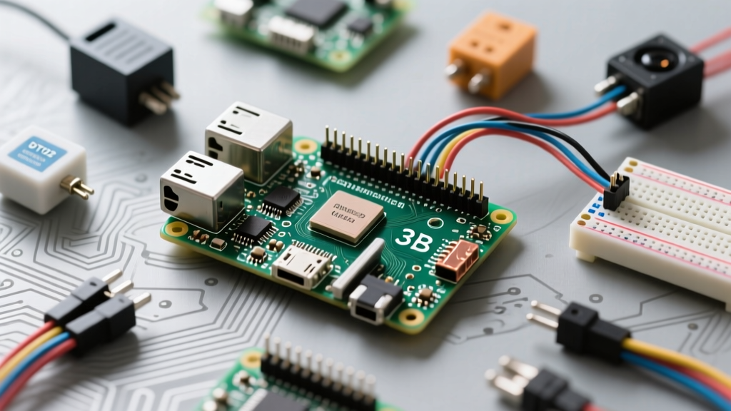
Even as newer, more powerful single-board computers flood the market, the Raspberry Pi 3 pins remain the gold standard for DIY electronics enthusiasts. The Model B and B+ variants introduced a robust 40-pin GPIO header that perfectly balanced processing power with physical interfacing capabilities. Here at ElectricalFlux, our community forums are filled with incredible builds that leverage this exact header. Rather than just listing a dry pinout diagram, we are diving into the real-world applications, wiring hurdles, and brilliant solutions our makers have developed using the Raspberry Pi 3's GPIO array.
Decoding the Raspberry Pi 3 Pins: Power vs. Logic
Before soldering a single wire, it is critical to understand the physical layout of the header. When you orient the Pi with the USB ports facing you, Pin 1 (the 3.3V power rail) is located on the top left, closest to the SD card slot. Pin 2 is the 5V rail. The board features eight dedicated Ground (GND) pins scattered across the header, a deliberate design choice by the Raspberry Pi Foundation to ensure makers never have to stretch a ground wire too far across a breadboard.
Out of the 40 physical pins, 26 are usable General Purpose Input/Output (GPIO) lines. The remaining pins are dedicated to power, ground, or specialized hardware interfaces like the I2C EEPROM ID pins (Pins 27 and 28). For software mapping, our community overwhelmingly recommends using the BCM (Broadcom SOC channel) numbering system rather than the physical BOARD numbering, as it aligns with the official Raspberry Pi Documentation and modern Python libraries like gpiozero.
Community Showcase: The Automated Hydroponics Rig
One of the most frequent questions on our forums is: 'How do I read analog soil moisture or pH sensors with the Pi 3?' The Raspberry Pi 3 pins are strictly digital; they can only read HIGH (3.3V) or LOW (0V). They lack the native Analog-to-Digital Converter (ADC) found on Arduino boards.
Community member @HydroHacker recently showcased a fully automated NFT hydroponics system that solves this elegantly. Instead of upgrading to a different microcontroller, they integrated an MCP3008 8-channel ADC via the Pi's SPI bus. This allows the Pi to read precise analog voltage data from up to eight different liquid sensors.
SPI Bus Mapping for the MCP3008 ADC
To replicate @HydroHacker's build, you must wire the MCP3008 to the dedicated SPI pins on the Raspberry Pi 3 header. Here is the exact mapping used in the community showcase:
- Pin 19 (GPIO 10 / MOSI): Master Out Slave In - Sends data from the Pi to the ADC.
- Pin 21 (GPIO 9 / MISO): Master In Slave Out - Receives the converted digital data from the ADC.
- Pin 23 (GPIO 11 / SCLK): Serial Clock - Synchronizes the data transfer.
- Pin 24 (GPIO 8 / CE0): Chip Enable - Tells the ADC to listen to the SPI bus.
By utilizing the spidev Python library, the community has managed to poll pH levels every 60 seconds with near-zero CPU overhead, proving that the Pi 3's specialized pins are just as valuable as its general-purpose ones.
Community Showcase: RetroPie Arcade Cabinet Controls
No discussion of the Raspberry Pi 3 pins is complete without mentioning the RetroPie community. Building a custom arcade cabinet requires mapping dozens of tactile push-buttons to digital inputs. A common beginner mistake is wiring a button between a GPIO pin and the 3.3V rail, requiring external pull-down resistors to prevent floating signals.
Our featured cabinet builder, @RetroBuilder, demonstrated the superior method: utilizing the Pi's internal pull-up resistors. By wiring one leg of the arcade button to Ground (e.g., Pin 6) and the other to a GPIO pin (e.g., Pin 11 / GPIO 17), the software can be configured to hold the pin HIGH internally.
'When I built my first bartop arcade, I used 15 external 10k resistors for my pull-ups. It was a wiring nightmare and three of them failed due to cold solder joints. Switching to the Pi 3's internal pull-ups via
GPIO.PUD_UPin Python saved me hours of debugging and made the harness infinitely more reliable.' — @RetroBuilder, ElectricalFlux Forums
The 5V Logic Trap: A Community Rite of Passage
If you browse our troubleshooting sub-forum, you will inevitably encounter the 'dead pin' phenomenon. The Raspberry Pi 3 operates on 3.3V logic. Feeding 5V into any of the GPIO pins will permanently damage the Broadcom BCM2837 silicon, often killing the entire board.
The most common culprit? The ubiquitous HC-SR04 Ultrasonic Distance Sensor. This sensor is cheap, widely available, and runs on 5V. While its Trigger pin can safely be driven by a 3.3V Pi pin, its Echo pin outputs a 5V HIGH signal when measuring distance.
Building a Hardware Voltage Divider
To safely interface the HC-SR04 with the Raspberry Pi 3 pins, our community mandates the use of a voltage divider on the Echo line. By placing two resistors in series, you can step the 5V down to a safe ~3.3V. The proven community standard uses a 330Ω resistor and a 470Ω resistor (as recommended by Adafruit's learning resources for similar logic-level shifting).
- Wire the HC-SR04 Echo pin to the 330Ω resistor.
- Connect the other end of the 330Ω resistor to your chosen Pi GPIO pin (e.g., Pin 16 / GPIO 23).
- Wire the 470Ω resistor between that same GPIO pin and a Ground pin (e.g., Pin 14).
This simple $0.05 circuit has saved countless Raspberry Pi 3 boards from the silicon graveyard.
Quick-Reference Pinout Table for Makers
For quick reference on the workbench, bookmark Pinout.xyz, but keep this community-curated table handy for the most frequently used Raspberry Pi 3 pins in DIY projects.
| Physical Pin | BCM GPIO | Default Function | Common Community Application |
|---|---|---|---|
| 1 | 3.3V Power | Power Rail | Powering low-draw sensors (e.g., DHT22) |
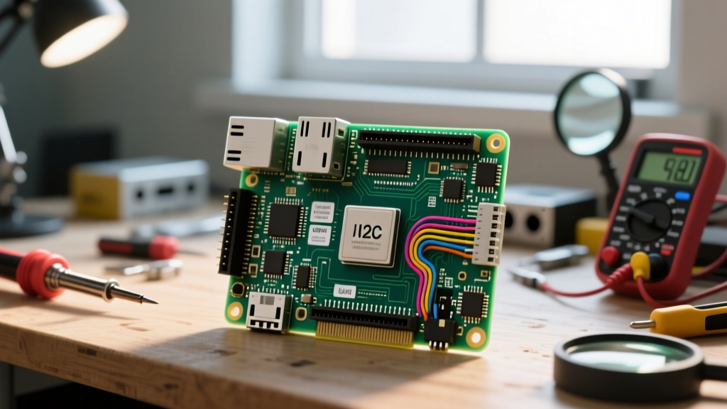
| 3 | 2 | I2C SDA | OLED Displays, BME280 Weather Sensors |
| 5 | 3 | I2C SCL | OLED Displays, BME280 Weather Sensors |
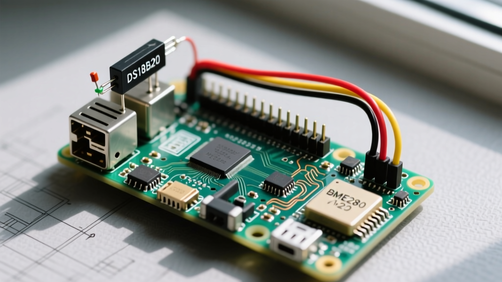
| 7 | 4 | GPIO / GPCLK0 | DS18B20 Temperature Probes (1-Wire) |
| 11 | 17 | GPIO | Arcade Buttons, Relay Triggers |
| 12 | 18 | GPIO / PWM0 | LED Dimming, Servo Motor Control |
| 40 | 21 | GPIO | Status LEDs, Button Inputs |
Final Thoughts from the Workbench
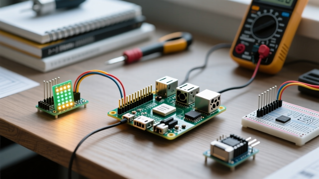
The Raspberry Pi 3 pins offer a masterclass in physical computing, provided you respect the electrical boundaries of the board. Whether you are multiplexing analog sensors via SPI, wiring up a retro gaming rig, or safely stepping down 5V logic, the community's collective trial-and-error has paved a smooth road for your next build. Always double-check your wiring with a multimeter before applying power, and never underestimate the utility of the eight dedicated ground pins. Happy making, and be sure to share your pinout discoveries on the ElectricalFlux community boards!