
The Great Pinout Confusion: BCM 0 vs. Physical Pin 27
When makers and engineers search for raspberry pi gpio0, they are usually confronting one of the most misunderstood designations on the 40-pin header. The confusion stems from a naming collision between the Broadcom (BCM) numbering system and the physical pin layout. BCM GPIO 0 maps to Physical Pin 27, while BCM GPIO 27 maps to Physical Pin 13. If you are probing Physical Pin 27 with a multimeter or writing a Python script using GPIO.setmode(GPIO.BCM) targeting pin 0, you are interacting with the ID_SD line—a highly specialized, hardware-reserved I2C data bus.
Unlike standard general-purpose pins, raspberry pi gpio0 is not meant for blinking LEDs or reading push buttons. It is a critical component of the Pi's hardware identification ecosystem. In this comprehensive hardware comparison, we will dissect how GPIO0 behaves across different Pi generations, the electrical realities of its pull-up resistors, and the severe failure modes that occur when this pin is misused in custom DIY projects.
Generational Hardware Comparison: Raspberry Pi GPIO0
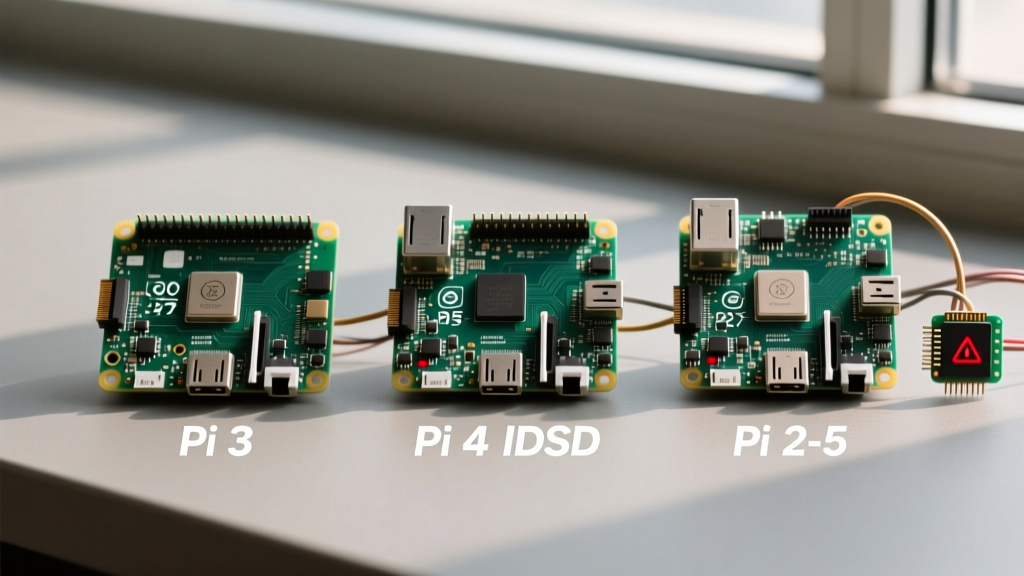
The internal routing and boot dependencies of BCM GPIO 0 (Physical Pin 27) have evolved significantly from the Pi 3 era to the modern RP1-based Pi 5. Below is a hardware comparison matrix detailing the architectural differences.
| Feature | Raspberry Pi 3B+ | Raspberry Pi 4B | Raspberry Pi 5 |
|---|---|---|---|
| BCM Assignment | BCM 0 (ID_SD) | BCM 0 (ID_SD) | RP1 GPIO 0 (ID_SD) |
| Physical Pin | 27 | 27 | 27 |
| Primary Function | HAT EEPROM I2C SDA | HAT EEPROM I2C SDA | HAT EEPROM I2C SDA |
| On-Board Pull-Up | 1.8kΩ to 3.3V | 1.8kΩ to 3.3V | 1.8kΩ to 3.3V (RP1) |
| Boot Dependency | Moderate (Overlays) | High (Power/Overlays) | Extreme (RP1 Config) |
| Southbridge Routed | No (Direct BCM2837) | No (Direct BCM2711) | Yes (Via RP1 Chip) |
Pi 3B+ Legacy Behavior
On the Pi 3B+, GPIO0 and GPIO1 (Physical Pins 27 and 28) were introduced primarily to support the HAT (Hardware Attached on Top) specification. The GPU firmware would read the EEPROM on the HAT during the early boot sequence to apply Device Tree Overlays (DTBO). If you accidentally wired a sensor to BCM 0 on a Pi 3, the boot process might slow down or fail to load a specific HAT driver, but the core OS would often still boot because the base power and clock configurations were hardcoded.
Pi 4B and the USB-C Power Matrix
The Pi 4B introduced a more complex power delivery system and PCIe-based USB 3.0 controller. While GPIO0 still serves as the ID_SD line, the data read from the HAT EEPROM can now dictate critical power limits and thermal throttling parameters. For instance, official PoE (Power over Ethernet) HATs use this I2C bus to communicate fan telemetry and power negotiation. Corrupting the I2C transaction on GPIO0 by attaching an external load can result in the Pi 4 incorrectly limiting USB current or failing to initialize the PoE fan controller.
Pi 5 and the RP1 Southbridge Architecture
The Raspberry Pi 5 represents a massive architectural shift. The BCM2712 SoC no longer directly manages the GPIO header; instead, it delegates this to the RP1 southbridge chip. On the Pi 5, raspberry pi gpio0 is routed through the RP1's internal I2C controller. The bootROM and early-stage firmware rely heavily on this bus to identify the Pi 5 Active Cooler, official power supplies, and specialized HATs. Because the RP1 handles all pin multiplexing, attempting to force GPIO0 into a standard output mode via user-space libraries like gpiod requires overriding the RP1's hardware-level reservations, which can lead to unpredictable bus lockups.
Electrical Characteristics and the HAT EEPROM Bus
To understand why raspberry pi gpio0 requires special handling, we must look at the electrical schematic. According to the Raspberry Pi HAT Design Guide, Pins 27 and 28 form a dedicated I2C0 bus. This bus features a 1.8kΩ pull-up resistor tied to the 3.3V rail on the Pi itself.
The target device on this bus is almost always an AT24C32 (32Kbit) I2C EEPROM located on the HAT, sitting at the reserved I2C address 0x50. The 1.8kΩ pull-up is relatively strong for an I2C bus, designed to ensure fast rise times despite the capacitance of the HAT connector and the EEPROM's input pins. If you connect a standard I2C sensor (like a BME280) to this bus alongside a HAT, you risk address collisions or bus capacitance exceeding the 400pF I2C standard limit, causing signal degradation and data corruption.
Expert Insight: Never use a standard logic analyzer or oscilloscope probe with high capacitance on Physical Pin 27 during the first 500 milliseconds of boot. The Pi's GPU firmware reads the EEPROM exactly once during early boot. If the signal is distorted by probing equipment, the Pi will assume no HAT is present and will silently skip critical hardware configurations.
Real-World Failure Modes When Misusing Pin 27
What happens if you ignore the warnings and wire a custom circuit to BCM GPIO 0? Based on field diagnostics and hardware teardowns, here are the most common failure modes:
- The Boot Loop of Death: If your external circuit pulls GPIO0 low (below 0.8V) during power-on, the Pi's firmware interprets this as a corrupted I2C bus or a shorted EEPROM. The Pi may enter a boot loop, continuously resetting as it fails to validate the hardware tree.
- Phantom HAT Detection: If your external circuit happens to mimic an I2C ACK signal or reflects noise that looks like EEPROM data, the Pi might load a random, incorrect Device Tree Overlay. This can disable the primary UART, reassign the audio codec, or completely break the primary I2C1 bus (Pins 3 and 5).
- Thermal Runaway (Pi 4/Pi 5): If a PoE HAT or Active Cooler is attached, and your custom wiring interferes with the
ID_SDline, the firmware loses telemetry. The Pi will default to a 'safe' fail-state, which often means running the fan at 100% duty cycle continuously or severely throttling the CPU clock speed to prevent overheating.
Software Overrides: Can You Force GPIO0?
Technically, yes. In the Raspberry Pi OS, you can attempt to reclaim BCM 0 by editing the /boot/firmware/config.txt file. By adding the line gpio=0=op,dh, you instruct the kernel to force the pin into an output mode and drive it high once the OS loads. Furthermore, you can disable the HAT probing entirely by adding force_eeprom_read=0.
However, from a hardware engineering perspective, this is strongly discouraged. You are fighting the firmware's native hardware abstraction layer. Any kernel update or EEPROM firmware patch can revert or ignore these overrides. For production environments or reliable DIY smart home nodes, relying on software overrides for reserved hardware pins is a recipe for maintenance nightmares.
Safe Alternatives for Advanced I2C Wiring
If you are looking at raspberry pi gpio0 because you have run out of I2C buses for your sensors, do not sacrifice the HAT bus. Instead, leverage the Pi's ability to create software I2C buses or enable alternative hardware I2C channels.
1. Enable Hardware I2C3 through I2C6
On the Pi 4 and Pi 5, the BCM chip supports multiple I2C controllers that are not exposed on the default 40-pin header but can be mapped to alternative GPIOs via overlays. For example, adding dtoverlay=i2c3,pins_4_5 to your config file safely routes I2C3 to BCM GPIO 4 and 5 without touching the reserved boot pins. You can verify these new buses using the i2cdetect -l command in the terminal.
2. Software I2C (Bitbanging)
If you only need to read a low-speed sensor (like a DHT22 or a basic light meter), use the i2c-gpio overlay. This allows you to assign any safe, unused GPIO pins (like BCM 17 and 27) to act as an I2C bus via software bitbanging. While it consumes slightly more CPU and lacks the hardware clock stretching of native I2C, it is 100% safe and guarantees zero interference with the Pi's boot sequence.
Final Verdict
The raspberry pi gpio0 (Physical Pin 27 / ID_SD) is a specialized, firmware-critical trace that should remain untouched in 99% of DIY projects. Its 1.8kΩ pull-up and strict boot-sequence timing make it wholly unsuitable for general-purpose input/output. By respecting the hardware boundaries of the RP1 and BCM architecture, and utilizing alternative I2C overlays, you ensure your Pi remains stable, your HATs function correctly, and your smart home infrastructure avoids catastrophic boot failures.
For a complete visual map of safe vs. reserved pins, always consult the Pinout.xyz GPIO0 database and cross-reference with the official Raspberry Pi hardware documentation before soldering your next custom PCB shield.