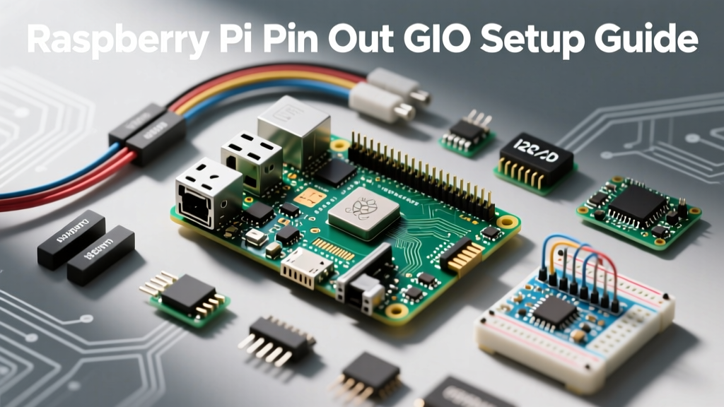

Understanding the Raspberry Pi pin out is the critical bridge between writing software and interacting with the physical world. Whether you are wiring up a simple DHT22 temperature sensor, configuring an I2C OLED display, or building a complex Home Assistant node with multiple relays, the 40-pin GPIO header is your primary interface. However, misinterpreting pin mappings or ignoring electrical limits can instantly destroy your single-board computer's System-on-Chip (SoC).
This setup and configuration guide goes beyond basic diagrams. We will cover the electrical realities of the 3.3V and 5V rails, the architectural shifts introduced in the Raspberry Pi 5, and the exact software configurations required to enable specialized communication buses.
Anatomy of the 40-Pin Header: Power, Ground, and GPIO
Since the release of the Model B+ in 2014, the physical Raspberry Pi pin out has remained remarkably consistent. The 40-pin header is divided into specific functional zones. Understanding these zones is vital for safe breadboarding and PCB design.
- Power Rails (5V): Pins 2 and 4 provide 5V directly from the USB-C input or the 5V GPIO pins. These are capable of supplying significant current, limited only by your power supply and the board's polyfuse (typically rated for 3A to 4A total board draw on the Pi 4 and Pi 5).
- Logic Rails (3.3V): Pins 1 and 17 output 3.3V. Warning: The 3.3V rail is generated by an internal Switched-Mode Power Supply (SMPS). On the Pi 4, the safe continuous external draw is limited to roughly 50mA across all 3.3V pins combined. Exceeding this causes voltage sag and unpredictable SoC brownouts.
- Ground (GND): Pins 6, 9, 14, 20, 25, 30, 34, and 39 are all tied to the common ground plane. Always use the GND pin physically closest to your signal pin to minimize loop inductance and reduce electromagnetic interference (EMI).
- GPIO & Multiplexed Pins: The remaining 26 pins are general-purpose I/O, which can be software-configured as digital inputs, outputs, or hardware PWM channels.
- EEPROM ID Pins: Pins 27 (GPIO0) and 28 (GPIO1) are reserved for HAT (Hardware Attached on Top) identification. Do not use these for general switching, as they are polled by the bootloader upon startup.
The Numbering Trap: BCM vs. BOARD
The most common point of failure for beginners configuring the Raspberry Pi pin out in Python is confusing the numbering schemes. When using libraries like RPi.GPIO or gpiozero, you must explicitly declare your mode.
BOARD Numbering (Physical)
This refers to the physical pin location on the header (1 through 40). It is hardware-agnostic and remains identical whether you are using a Pi 3B+, Pi 4, or Pi 5. If you are looking straight down at the Pi with the USB ports facing you, Pin 1 is the top-left 3.3V pin, and Pin 2 is the top-right 5V pin.
BCM Numbering (Broadcom SOC Channels)
This refers to the internal GPIO channel numbers of the Broadcom (or RP1) silicon. For example, Physical Pin 3 is BCM GPIO 2. Physical Pin 29 is BCM GPIO 5. When reading official Raspberry Pi GPIO documentation, BCM numbering is the standard. We strongly recommend defaulting to BCM numbering in your code, as it maps directly to the underlying hardware registers and device tree overlays.
Configuring Interfaces: I2C, SPI, and UART Mapping
The Raspberry Pi pin out dedicates specific pins to hardware communication protocols. By default, some of these interfaces are disabled in the operating system to free up the pins for standard GPIO use and to prevent boot conflicts.
Enabling I2C (Inter-Integrated Circuit)
I2C is the standard for connecting low-speed peripherals like BME280 environmental sensors or SSD1306 OLED displays.
- Physical Pins: SDA is on Physical Pin 3 (BCM 2). SCL is on Physical Pin 5 (BCM 3).
- Configuration: Open your terminal and run
sudo raspi-config. Navigate to Interface Options > I2C and enable it. - Hardware Note: The Pi includes 1.8kΩ internal pull-up resistors on the I2C lines. If you are running a long I2C bus (over 30cm) or connecting more than three devices, you must add external 4.7kΩ pull-up resistors to the 3.3V rail to maintain signal integrity.
Enabling SPI (Serial Peripheral Interface)
SPI is required for high-speed data transfer, such as driving TFT LCD screens or reading high-resolution ADCs (Analog-to-Digital Converters).
- Physical Pins: MOSI (Pin 19), MISO (Pin 21), SCLK (Pin 23), CE0 (Pin 24), and CE1 (Pin 26).
- Configuration: Enable via
sudo raspi-configunder Interface Options > SPI. - Throughput Note: The hardware SPI clock can be pushed up to 125MHz on the Pi 4, but practical wiring on a breadboard will introduce capacitance that limits stable operation to around 10MHz–20MHz without logic level buffering.
Raspberry Pi Pin Out Reference Table (Core GPIO)
Below is a structured reference mapping the physical board pins to their Broadcom (BCM) equivalents and default alternate functions. This table focuses on the most frequently used pins for DIY electronics and smart home integrations.
| Physical Pin | BCM GPIO | Default Function | Hardware Feature | Common Use Case |
|---|---|---|---|---|
| 3 | 2 | SDA1 | I2C Data | OLED Displays, Sensors |
| 5 | 3 | SCL1 | I2C Clock | OLED Displays, Sensors |
| 7 | 4 | GPIO4 | 1-Wire Data | DS18B20 Temp Probes |
| 8 | 14 | TXD | UART Transmit | GPS Modules, Zigbee |
| 10 | 15 | RXD | UART Receive | GPS Modules, Zigbee |
| 11 | 17 | GPIO17 | General I/O | Relay Control, Buttons |
| 12 | 18 | GPIO18 | Hardware PWM0 | LED Dimming, Servos |
| 15 | 22 | GPIO22 | General I/O | Pir Motion Sensors |
| 16 | 23 | GPIO23 | General I/O | Motor Driver Direction |
| 18 | 24 | GPIO24 | General I/O | Motor Driver Step |
| 22 | 25 | GPIO25 | General I/O | Status LEDs |
| 29 | 5 | GPIO5 | General I/O | Interrupt Pins |
| 31 | 6 | GPIO6 | General I/O | Encoder Inputs |
| 32 | 12 | GPIO12 | Hardware PWM0 | Secondary PWM Fan |
| 33 | 13 | GPIO13 | Hardware PWM1 | Audio Output (DAC) |
The Pi 5 Architecture Shift: Enter the RP1 Southbridge
If you are configuring a Raspberry Pi 5, the physical pin out remains 100% backward compatible with the Pi 4. However, the underlying silicon architecture has fundamentally changed. The Pi 5 offloads GPIO, I2C, SPI, and UART handling from the main Broadcom BCM2712 CPU to a dedicated RP1 southbridge chip.
Information Gain for Developers: Because the RP1 handles the I/O, the memory-mapped GPIO addresses have changed. Legacy C/C++ code that directly manipulates the
/dev/memregisters (bypassing the kernel) written for the Pi 3 or Pi 4 will fail or crash on the Pi 5. Always use the officiallibgpiodlibrary or the updatedgpiozeroPython wrappers, which abstract the hardware layer and ensure compatibility across the RP1 and Broadcom architectures.
Furthermore, the Pi 5 RP1 chip supports higher drive strengths and features improved 5V-tolerant input thresholds on specific pins, though treating the entire header as strictly 3.3V logic remains the golden rule for hardware longevity.
Wiring Best Practices and Failure Mode Prevention
The most catastrophic failure mode when working with the Raspberry Pi pin out is the 3.3V vs 5V Logic Level Trap. The GPIO pins operate strictly at 3.3V logic. Feeding a 5V signal into any GPIO pin (such as the TX line from an Arduino or a 5V HC-SR04 ultrasonic sensor) will forward-bias the internal ESD protection diodes. This dumps 5V directly into the 3.3V core logic rail, instantly and permanently frying the SoC.
Implementing Safe Level Shifting
When interfacing 5V components with the Pi, you must use a logic level converter. Do not rely on simple resistor voltage dividers for high-speed buses like SPI or I2C, as the parasitic capacitance will round off the square waves, causing data corruption.
Instead, use a dedicated MOSFET-based level shifter IC, such as the BSS138 or the Texas Instruments TXS0108E. The Adafruit 4-Channel Level Shifter Breakout is a reliable, pre-packaged solution that safely translates 3.3V Pi signals to 5V sensor signals without risking back-voltage leakage.
Managing Inductive Kickback
If your pin out configuration involves driving mechanical relays or small DC motors, you must account for inductive kickback. When the GPIO pin goes LOW, the collapsing magnetic field in the relay coil generates a massive reverse voltage spike. Always wire a flyback diode (such as a 1N4007) in reverse parallel across the relay coil. Furthermore, never drive a relay coil directly from a Pi GPIO pin; the coil requires 70mA+, which exceeds the 16mA per-pin limit. Always use an NPN transistor (like a 2N2222) or an optocoupler to isolate the Pi from the high-current load.
Software Tools for Pin Verification
Before physically wiring a new project, verify your pin mappings using the built-in CLI tools provided by Raspberry Pi OS. Open your terminal and simply type:
pinoutThis command renders a beautiful, color-coded ASCII diagram of the Raspberry Pi pin out directly in your terminal, complete with BCM mappings, board revision details, and RAM size. For programmatic verification in Python scripts, utilize the gpiozero pin factory inspection tools to ensure your software definitions match your physical jumper wires before applying power to your breadboard.