
The Anatomy of the 40-Pin Header
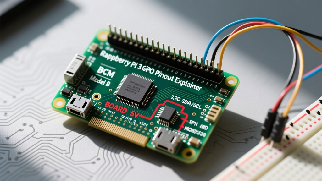
When transitioning from traditional 8-bit microcontrollers like the Arduino Uno to Linux-based single-board computers (SBCs), understanding the physical hardware interface is your first major hurdle. The GPIO Raspberry Pi 3 pinout revolves around a 2x20 male header located on the top-left edge of the PCB. Whether you are using the Pi 3 Model B or the B+, the physical layout remains identical, governed by the Broadcom BCM2837 System-on-Chip (SoC).
Out of the 40 physical pins, only 26 are actual programmable General Purpose Input/Output (GPIO) lines. The remaining 14 pins are dedicated to power delivery and grounding. Specifically, you will find two 3.3V power pins (Pins 1 and 17), two 5V power pins (Pins 2 and 4), and eight Ground (GND) pins distributed across the header to minimize return-path inductance in high-speed digital circuits.
Decoding the Numbering Systems: BCM vs. BOARD
The most frequent stumbling block for makers writing Python scripts via the RPi.GPIO or gpiozero libraries is the dual-numbering paradigm. To master the GPIO Raspberry Pi 3 pinout, you must understand the difference between BOARD and BCM numbering.
- BOARD Numbering: This refers to the physical pin number on the header, counting from 1 to 40. It is hardware-agnostic and easy to trace with a multimeter. For example, the top-left 3.3V pin is BOARD 1, and the pin directly below it is BOARD 3.
- BCM Numbering: This refers to the Broadcom SOC channel numbers. These are the internal hardware register addresses used by the SoC. For instance, physical BOARD Pin 11 corresponds to BCM GPIO 17. If you read the official Raspberry Pi hardware documentation, you will see that Broadcom numbering is the native language of the silicon.
Best Practice: Always use BCM numbering in your code. It aligns with the underlying Linux sysfs and device tree mappings, making it significantly easier to troubleshoot kernel-level I2C or SPI overlays.
The 3.3V Logic Reality Check
Unlike the ATmega328P on an Arduino Uno which operates at a forgiving 5V logic level, the BCM2837 SoC is strictly a 3.3V device. Applying 5V to any GPIO pin will instantly and permanently destroy the SoC's internal ESD protection diodes, effectively bricking the board.
Furthermore, current sourcing capabilities are vastly different from standard MCUs. While an Arduino pin can safely source 20mA to 40mA, a Raspberry Pi 3 GPIO pin has an absolute maximum rating of 16mA. More critically, the total current draw across all GPIO pins in a single bank must not exceed 50mA. If you attempt to drive a standard 5V relay module directly from a Pi GPIO pin, you will likely brown out the SoC or trigger thermal throttling. Always use a logic-level MOSFET (like the IRLZ44N) or an optocoupler to isolate high-current inductive loads.
Special Function Pins and Protocol Defaults
Beyond standard digital toggling, the GPIO Raspberry Pi 3 pinout exposes dedicated hardware peripherals. According to the comprehensive mapping on Pinout.xyz, the default alternate functions are hardcoded via the device tree:
I2C (Inter-Integrated Circuit)
Physical Pin 3 (BCM 2) is SDA1, and Physical Pin 5 (BCM 3) is SCL1. The Raspberry Pi board includes onboard 1.8kΩ pull-up resistors tied to the 3.3V rail. When connecting 5V I2C sensors (like the classic Arduino LCD backpacks), you must disable the Pi's internal pull-ups and use an external I2C level shifter to prevent 5V back-feeding into the 3.3V rail.
SPI (Serial Peripheral Interface)
SPI0 is broken out on the right side of the header: MOSI (BCM 10), MISO (BCM 9), SCLK (BCM 11), and two Chip Select lines, CE0 (BCM 8) and CE1 (BCM 7). SPI is highly recommended over I2C for high-bandwidth peripherals like TFT displays or ADCs, as it avoids the strict capacitance limits of the I2C bus.
The Raspberry Pi 3 UART Trap
A highly specific architectural quirk of the Pi 3 series involves the Universal Asynchronous Receiver-Transmitter (UART). On older Pi models, the hardware UART (ttyAMA0) was mapped directly to the GPIO header (Pins 8 and 10). However, on the Pi 3, the primary hardware UART was rerouted to feed the onboard Bluetooth module.
The GPIO header was instead given the 'mini UART' (ttyS0), which lacks a dedicated baud-rate clock and ties its speed to the core GPU frequency. This results in corrupted serial data when CPU throttling occurs. To restore the hardware UART to the GPIO header for reliable communication with external MCUs, you must edit your configuration file. Add the following line to your /boot/firmware/config.txt (or /boot/config.txt on older OS versions):
dtoverlay=disable-btAs detailed in the official device tree parameters guide, this disables Bluetooth but restores stable, hardware-backed serial communication on BCM 14 (TXD) and BCM 15 (RXD).
Safely Interfacing 5V Arduino Modules
The maker community is saturated with 5V Arduino modules (HC-SR04 ultrasonic sensors, NeoPixels, 5V logic relays). To safely integrate these with the 3.3V GPIO Raspberry Pi 3 pinout, you must use a bidirectional logic level converter. The TXS0108E IC or a discrete BSS138 MOSFET circuit are the industry standards. These components safely translate the 3.3V output from the Pi to a 5V HIGH signal for the peripheral, and step down the 5V return signal to a safe 3.3V logic level for the Pi's input pins.
Essential Pin Mapping Reference Table
Keep this quick-reference table on your workbench when wiring up new peripherals to the Pi 3:
| Physical Pin | BCM GPIO | Default Function | Hardware Notes |
|---|---|---|---|
| 1 | N/A | 3.3V Power | Max 50mA total draw |
| 3 | 2 | I2C SDA1 | 1.8k pull-up to 3.3V |
| 5 | 3 | I2C SCL1 | 1.8k pull-up to 3.3V |
| 8 | 14 | UART TXD | Requires disable-bt overlay on Pi 3 |
| 10 | 15 | UART RXD | Requires disable-bt overlay on Pi 3 |
| 11 | 17 | Standard GPIO | Safe for digital input/output |
| 19 | 10 | SPI MOSI | Master Out Slave In |
| 21 | 9 | SPI MISO | Master In Slave Out |
By respecting the voltage limits, understanding the BCM mapping, and properly configuring the device tree overlays, the Raspberry Pi 3 becomes an incredibly powerful hub for bridging Linux-based network operations with low-level hardware control.